

Shenzhen Southern Machinery - SMT / THT equipment design and manufacturing since 2011
Southern Machinery Southern MachinerySMT / THT equipment and feeders
Bulk feeding - no packaging required

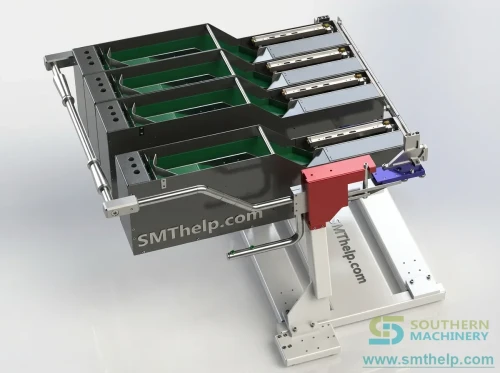
Reciprocating Belt Feeder
for Smart EMS PCB Assembly

The S-MVF01 takes loose odd-form components straight from the bag and presents them, oriented, at a pick position your placement machine can reach. No tape, no tube, no tray, no bowl feeder footprint.

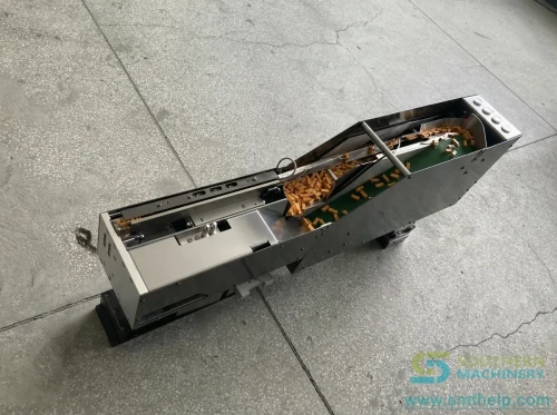
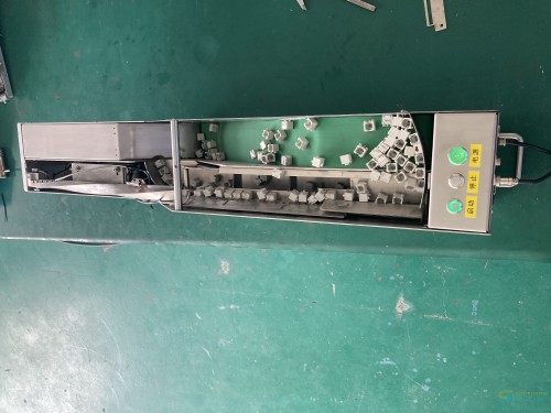
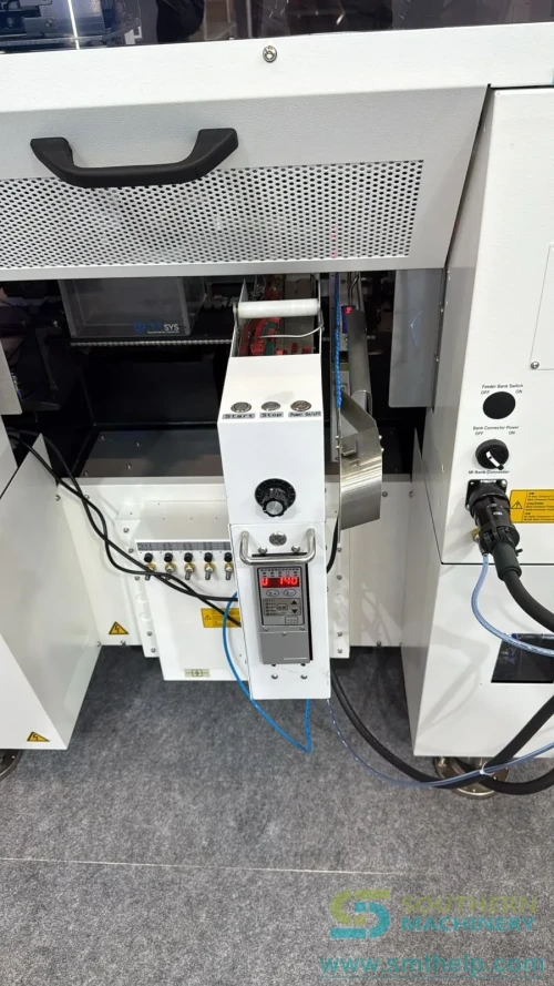
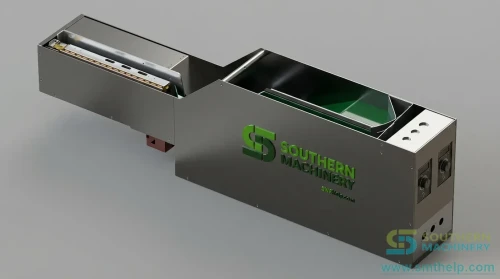
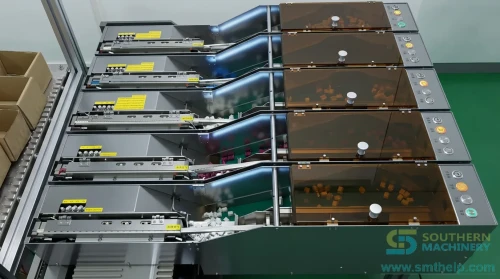
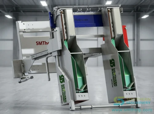
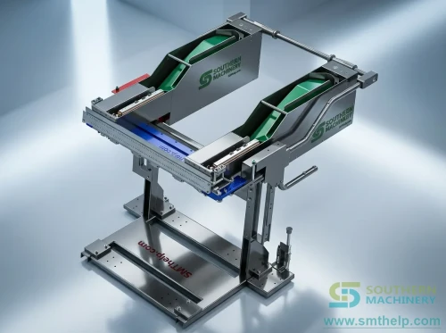
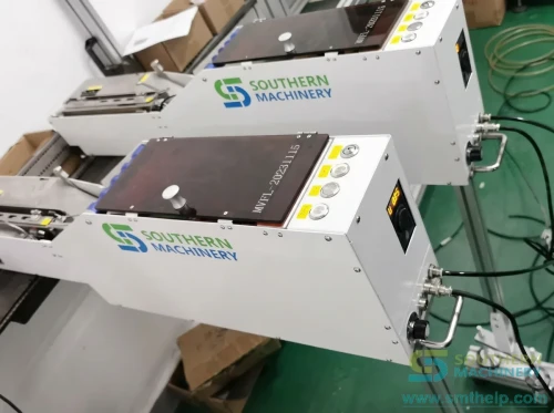
S-MVF01 bulk belt feeder with loose terminals in the open belt trackBulk belt feeder seen from above with loose metal parts along the belt trackThe feeder housing photographed at an angle, open top channel visibleBulk components in the material box at the loading end of the feederS-MVF01 feeder installed in the feeder port of a placement machine
850 x 140 x 260 mm
Footprint - smaller than a bowl feeder
3 x 3 x 3 - 20 x 20 x 20 mm
Component envelope handled
1.5 - 2 s
Published feeding interval
+/-1 mm
Published feeding accuracy
Specification values attributed to their source documentConflicting values disclosed, not averagedUnconfirmed values marked To be confirmed
Why bulk feeding

Packaging is a cost you pay three times

You pay to have the part taped or tubed, you pay to store the packaging, and you pay again in floor space and changeover time. Bulk feeding removes all three - but only for the parts that can actually be handled loose.

01

No tape, no tube, no tray

Components are loaded loose. There is no carrier tape to buy, no reel to store and no packaging waste to dispose of, so the per-part cost of the packaging line disappears.

02

A footprint a bowl feeder cannot match

At 850 x 140 x 260 mm and 12 kg the feeder sits in the machine feeder bank. A vibratory bowl feeder with comparable reach usually needs its own floor space and its own guarding.

03

One unit, several part numbers

A dedicated bulk feeder is normally built around one part. This one is designed for multi-pin odd-form components as a family, so a changeover is a track adjustment rather than a new feeder.

How it feeds

From loose parts in a box to an oriented part at the nozzle

The mechanism is mechanical selection plus directed vibration: the belt lifts parts out of the box, a selection track keeps the ones that are correctly oriented, the belt return sends the rest back, and direct vibration carries the accepted part to the pick position.

Loose bulk components sitting in the open belt track of the feeder, photographed on the factory floor
Bulk belt feeder seen from above with loose metal parts spread along the belt track
01

Load loose parts

Components go into the material box straight from the bag. No orientation is required from the operator.

02

Belt lift

A motor-driven belt carries parts up out of the box toward the selection track.

03

Air assist

Five blowing points move parts along: out of the box, into the selection area, and toward the belt.

04

Selection track

The track admits parts in a usable orientation and rejects the rest, so orientation is mechanical, not manual.

05

Belt return

Rejected parts travel back on the return track and re-enter the cycle instead of stopping the feeder.

06

Direct vibration

An accepted part is advanced to the pick position by a straight-vibration track, not by the belt.

07

Part present

A fibre-optic sensor confirms a part is at the position before the machine is asked to pick.

08

Hold at the nozzle

A vacuum suction block at the track front holds the part steady so it cannot drift forward or back.

09

Refill and repeat

The operator tops the box up. The published test record is 1000 continuous feeds, then 48 hours of ageing.

Sequence described from the principle stated on the S-MVF01 specification sheets and the station descriptions in the user manual. The exact track geometry is configuration dependent.

LOAD
SELECT
PRESENT
Load - select - return rejects - present at the nozzle
Platform fit

Three things decide whether it drops into your line

A feeder is only useful if it physically mounts, electrically talks to the machine, and holds the part long enough for the nozzle to take it. Each of those is a documented feature, not an assumption.

Source: S-MVF01 specification sheets and the Reciprocating Feeder user manual
S-MVF01

Any-brand placement machine

The sheet states the feeder can be equipped to any brand of placement machine. Field photographs in the Southern Machinery image library show it installed in a JUKI feeder port.

S-MVF01

Two control modes

The feeder supports IO communication with the host, or it can run self-controlled with no communication at all - useful when the machine has no spare feeder interface.

S-MVF01

Mounting that is not a one-off bracket

Positioning key plus clamping block, with support for other fixing structures. The manual shows the belt module released by removing its tensioning screws.

Specification

Specification with sources

Every row names the document the value was read from. Where the two specification sheets disagree, both values are shown side by side - read the Open points section before you quote.

Source: three supplied documents, quoted as written
Parameter Specification sheet - Reciprocating Belt Feeder Specification sheet - Belt Bulk Feeder Reciprocating Feeder user manual
Model codeS-MVF01S-MVF01Not stated
Machine typeBelt bulk feeder for SMT mountersBelt bulk feeder, THT odd form to SMT mounterReciprocating feeder
Dimensions (L x W x H)850 x 140 x 260 mm850 x 140 x 260 mmNot stated
Weight12 kg12 kgNot stated
Component typesConnector, buzzer, network port, terminal, square capacitorConnector, buzzer, mesh port, terminal post, square capacitorOdd-form components and multi-pin leads
Component size3 x 3 x 3 mm to 20 x 20 x 20 mm3 x 3 x 3 mm to 20 x 20 x 20 mmNot stated
Components that suit the feederDistinct characteristics, physically distinguishableDistinct characteristics, physically distinguishableParts the selection track can orient mechanically
Components to avoidNo obvious physical features and needing direction; leads easily deformed; length to height ratio under 1:1.2No obvious physical features and needing direction; leads easily deformed; length to height ratio under 1:1.2Parts that cannot be distinguished by the selection track
Packaging acceptedBulkBulkBulk
Feeding principleSelection track; rejected parts return on the belt return; accepted parts advanced by direct vibrationSelection track with component reflux; belt return and direct vibration to the pick levelBelt track plus straight-vibration track
Material positioningFibre-optic induction plus direct vibration delayFibre-optic induction plus direct vibration delayFront and rear track sensors plus a vacuum suction block
Fixing methodPositioning key plus clamping block, supports other fixing structuresPositioning key plus pressing block, supports other fixed structuresInstall the dowel pins, then clamp
Operating voltage220 V / 50 Hz220 V / 50 HzAC 220 V, 50 Hz
Average current / peak current3 A / 6 A3 A / 6 ANot stated
Working air pressure0.4 - 0.6 MPa0.4 - 0.6 MPaUsable air pressure above 0.5 MPa
OperationKey operationButton operationStart, stop and power buttons with status lights
Host connection8-core 16 mm aviation plug8-pin 16 mm aviation plugCommunication port for material-present and alarm signals
CommunicationIO communication, or self-control with no communicationIO communication, or self-control with no communicationHost signal interaction: material present, alarm
ControllerBased on Mitsubishi (PLC control)PLC, programmable control circuitPLC control board plus motor speed control board and motor adapter board
Drive motor maximum speed500 rpm500 rpmAdjustable on the speed controller
Feeding speed1.5 - 2 s1.5 - 2 sNot stated
Feed channelSingle channelSingle channelSingle channel
Speed adjustmentPromise debuggingInfinitely variable speed regulationSpeed controller: clockwise increases, counterclockwise decreases; vibration frequency set per channel
Feeding accuracy+/-1 mm+/-1 mmNot stated
Continuous feeding test1000 feeds without abnormality1000 feeds without abnormalityNot stated
Ageing test48 hours continuous without abnormality48 hours continuous without abnormalityNot stated

Parameter by parameter, with the document it came from

All 26 rows are reproduced from the supplied documents. Where a document does not state a parameter, the row says so rather than borrowing a value from another model.

Open points

Where the documents disagree, both values stay on the page

A specification table that quietly picks one of two numbers is worth less than one that shows both. Six parameters below do not agree across the supplied documents, or are stated in only one of them. Confirm each against the current drawing for your configuration before you place an order.

Status: To be confirmed - not averaged, not silently resolved
Parameter Specification sheet User manual What the difference means Status
Speed adjustmentReciprocating sheet: promise debugging. Bulk sheet: infinitely variable speed regulation.Speed controller with clockwise increase, plus per-channel vibration frequency.Two different descriptions of the same control, and the manual adds a second adjustment layer.To be confirmed
Feeding speed vs cycle timeBulk sheet summary quotes cycle time of 1 s or less; both sheets quote a feeding speed of 1.5 - 2 s.Not statedA cycle time of 1 s and a feeding interval of 1.5 - 2 s cannot both describe the same motion.To be confirmed
Working air pressureBoth sheets state 0.4 - 0.6 MPa.Usable air pressure above 0.5 MPa.The manual gives a floor of 0.5 MPa, the sheets a band starting at 0.4 MPa.To be confirmed
Dimension unitReciprocating sheet prints 850 x 140 x 260 m; bulk sheet prints 850 x 140 x 260 mm.Not statedThe metre unit on the reciprocating sheet is a typographical slip; the numbers agree.To be confirmed
ControllerReciprocating sheet names Mitsubishi; the bulk sheet says only PLC.Lists a PLC control board, a motor speed control board and a motor adapter board, with no brand.The controller brand is stated in one document only, so it is not treated as confirmed.To be confirmed
Model namingTwo supplied sheets carry the same code S-MVF01 under two different titles.The manual is titled Reciprocating Feeder without a model code.The Southern Machinery feeder catalogue also lists a separate SBF2002 Reciprocating Belt Feeder.To be confirmed

This page is not a quotation. Values are reproduced from the documents named in each row; the current drawing for your configuration governs.

Throughput

What a single channel is worth per hour

The feeder is single channel, so the upper bound is set by the published feeding interval. The table converts that interval into feeds per hour at three realistic availability levels.

Derived from the published 1.5 - 2 s feeding interval
Feeding intervalTheoretical feeds/hourAt 90 percent availabilityAt 80 percent availability
1.5 s240021601920
1.75 s205718511646
2.0 s180016201440

Derived arithmetic, not a measured production figure. It counts feeds, not finished boards: the machine cycle, the number of bulk parts per board and the operator's refill interval all sit on top of it.

Configuration

What you choose when you order

Each of these is a documented feature of the platform rather than a custom engineering project.

Source: S-MVF01 specification sheets and the Reciprocating Feeder user manual

Belt return module

Sends rejected and surplus parts back into the cycle instead of leaving them in the track.

Vacuum suction block

Holds the accepted part at the front of the track. The manual notes the vacuum switches off by itself after a minute if the part is not taken.

Five-point air blowing

Separate blowing points for box exit, selection assistance, fallen parts, selection entry and final delivery.

Fibre-optic and track-end sensing

Part-present sensing plus front and rear track sensors, which stop the vibrator and the belt when the track is full.

Host interface

8-core 16 mm aviation plug carrying material-present and alarm signals, or self-control with no host link.

Quick-release belt module

The manual documents removing the tensioning screws to take the belt module off for cleaning or replacement.

Commissioning

Six steps from crate to first accepted part

The manual describes the machine as a sequence: power on, air on, then adjust. These are the six stations in that order.

STEP 1

Mount and clamp

Locate on the positioning key, then clamp. Confirm the feeder sits square in the feeder bank before you tighten.

STEP 2

Air on

Clean, dry air. The sheets give a 0.4 - 0.6 MPa band; the manual asks for more than 0.5 MPa.

STEP 3

Power on

AC 220 V, 50 Hz. The internal switching supply is DC 24 V, 100 W, feeding the PLC and the motors.

STEP 4

Connect or isolate

Either wire the aviation plug for IO communication, or leave it self-controlled and let the operator start it.

STEP 5

Tune the two channels

Channel A sets the selection box frequency, channel B the feeding track. Then set belt speed on the speed controller.

STEP 6

Prove it

Run 1000 consecutive feeds, then a 48-hour ageing run. Those are the published acceptance figures.

850 x 140 x 260 mm 12 kg AC 220 V / 50 Hz 0.4 - 0.6 MPa +/-1 mm Single channel

Installation is a qualified task. The manual assumes the machine is de-energised and the air supply isolated before any panel is opened or any belt is tensioned.

Payback

Work out the payback from your own numbers

Nothing on this page asserts a saving. The two machine values are the published feeding interval and the component count you enter; everything else is yours to set. If the machine time is not shorter than the manual time, the page says so instead of printing a negative.

Bulk feeding payback

Enter your own labour rate and component mix

Machine time per board
— s
Handling hours released
— h / month
Labour released
— USD / year
Payback
—
Illustrative model, not a quotation. Machine time uses the published 1.5 - 2 s feeding interval. The model ignores material cost, packaging cost, quality yield and machine utilisation, all of which affect the real answer.
Working video

The feeder running

Selected from the Southern Machinery YouTube board. Titles and running times are the board's own, not re-worded here.

Insights

Eight notes on feeding parts that arrive loose

Long-form notes on bulk feeding, written for process engineers and production managers who have to make the decision, not just read about it.

ARTICLE 01Loose Parts in a Bag Are a Line-Balancing Problem, Not a Purchasing Problem

The cheapest part number on the quotation can be the most expensive one on the floor.

Full articles are in English. The summary above carries the argument in your language.

A purchasing team compares three quotations for the same odd-form connector and picks the cheapest unit price. The part arrives taped, on reels, at a good rate. Six weeks later the line is running at 78 percent of the rate the quotation assumed, and nobody can point at the number that went wrong, because the number that went wrong is not on the quotation at all.

The cost is not in the part. It is in the tape. Someone had to pay a supplier to tape it, someone has to receive and store the reels, someone has to change the reel mid-shift, and someone has to dispose of the carrier tape afterwards. Then the tape imposes its own constraint: the reel only holds so many parts, so the machine stops when the reel empties rather than when the board is finished. Every one of those costs lands on the floor, and none of them appear next to the unit price.

Do the comparison on a per-board basis instead. Take the part price, add the packaging surcharge the supplier charges for taping, add the handling minutes per reel multiplied by the fully loaded labour rate, and add the changeover stops per shift multiplied by the line rate. The number that comes out is the real cost, and it is frequently 15 to 30 percent above the unit price you started with.

That is where bulk feeding changes the arithmetic rather than the price. A bulk feeder accepts the part loose, so the taping surcharge disappears, the reel handling disappears, and the feeder refills from a box instead of stopping on an empty reel. On the S-MVF01 the component envelope runs from 3 x 3 x 3 mm to 20 x 20 x 20 mm and the unit is 850 x 140 x 260 mm, so it fits in a feeder bank where a bowl feeder would need floor space.

The habit to build is a quarterly review of which parts are still arriving taped. As the mix moves, a part that was high volume last year may now be a 40-board-per-week job, and it is still paying a taping surcharge and a reel changeover for the privilege. Move the low-volume odd-form parts to bulk, keep the genuinely high-volume ones on tape, and re-check the split every quarter.

Pick the three odd-form part numbers with the worst per-board cost and ask for a bulk-feeding trial on those three. Send a sample bag of each; the answer will be a feeder configuration or a straight no, and both are useful. Start with the sample bag, not the purchase order.

ARTICLE 02What a Bowl Feeder Really Costs After the Third Part Number

A bowl feeder is priced per part. That is fine until the part mix changes.

Full articles are in English. The summary above carries the argument in your language.

A vibratory bowl feeder is a beautiful piece of engineering. It is also, in most factories, a single-part machine with a footprint and a price to match, and that combination only works while the part it was built around stays in production.

The problem arrives with the third part number. The first bowl feeder was specified for the connector you were building in volume. The second was justified because the first could not be retooled quickly. By the third, you are paying for three bowl feeders, three footprints, three sets of tooling, and three sets of spare tooling, and each one sits idle whenever its part is not running. The tooling cost is real, but the idle footprint is what actually hurts, because floor space near the line is the scarcest thing you own.

Model the changeover cost rather than the capital cost. For each candidate part, write down the retooling time, the retooling cost, the annual volume, and the number of hours per year the feeder would sit idle. Any part that would idle more than half the year is a bad candidate for a dedicated machine, no matter how good the unit price looked.

The alternative is a feeder that is built around a component family instead of a single part. The S-MVF01 handles multi-pin odd-form components as a family and presents them through a selection track rather than a dedicated bowl, so a changeover is a track adjustment rather than a new feeder. It also occupies 850 x 140 x 260 mm at 12 kg, which is small enough to live in the machine's feeder bank instead of on the floor.

The recurring question to put on the engineering agenda is simple: which of our dedicated feeders is currently the wrong machine for its part? That question gets asked every time the mix shifts, and it is much cheaper to answer than to discover during a capacity review.

Take the part with the lowest annual volume that still has a dedicated feeder, and price a family-based feeder against the idle hours. If the idle hours do not justify it, keep the dedicated machine - and write down the reason, so the next review does not relitigate it.

ARTICLE 03How to Tell Whether an Odd-Form Part Can Be Fed Without Packaging

Three physical tests you can run on a sample bag before anyone quotes a feeder.

Full articles are in English. The summary above carries the argument in your language.

Before anyone quotes a feeder, you can run three tests on a sample bag that will tell you whether bulk feeding is plausible. None of them need a machine, and all three take under an hour.

The reason this matters is that bulk feeding fails for physical reasons, not commercial ones. A part fails because the selection track cannot tell one orientation from another, because the leads bend when parts tumble together, or because the part is so tall and narrow that it will not lie down reliably. Those are properties of the part, and they are visible in a bag on a bench.

Test one is the orientation test. Empty the bag onto a tray, and try to sort the parts into piles by orientation using only a spatula. If a person cannot do it quickly by feel and by eye, a mechanical track will not do it either. Test two is the tumbling test. Shake the bag for a minute and inspect the leads for deformation. Test three is the aspect test: measure the length and the height of the part and divide them. The specification sheets for the S-MVF01 rule out anything under 1:1.2.

Run the same three tests against the published envelope. The S-MVF01 accepts components from 3 x 3 x 3 mm to 20 x 20 x 20 mm, and it explicitly excludes parts with no obvious physical feature that still need to be oriented, parts whose leads deform easily, and parts below the 1:1.2 aspect ratio. Those three exclusions are on the sheet because they are the three ways bulk feeding actually fails.

Make the test part of how new parts are introduced, not part of how feeders are bought. A ten-minute bag test at the design stage is worth more than a week of debugging after the feeder is installed, and it gives the design team a concrete reason to add a chamfer or a flat.

Pick one candidate part, run the three tests, and photograph the result. Send the photographs with the sample bag. A clear photograph of the part lying in three orientations will get you a faster and more honest answer than a specification sheet alone.

ARTICLE 04Six Checks Before You Cut Packaging From an Odd-Form Part

A short acceptance routine that stops a bulk conversion from failing on the line.

Full articles are in English. The summary above carries the argument in your language.

Cutting packaging out of an odd-form part is one of the highest-return changes available to an EMS line, and it is also one of the easiest to get wrong, because the failure usually shows up two weeks after the changeover as an intermittent jam rather than as an obvious mistake.

The failure pattern is consistent. Someone proves the feeder on a clean sample of parts, the changeover is approved, and then production starts using parts from a different batch. The new batch has a slightly different flash on the moulding, or the leads are a fraction straighter, and the selection track that worked perfectly now rejects one part in fifty. Nobody suspects the part, because the feeder was proven.

The answer is to accept the conversion formally, with six checks. First, the orientation test on three separate batches, not one. Second, the lead-deformation test after tumbling. Third, the aspect ratio measured on ten samples, not one. Fourth, a continuous run of at least 1000 feeds. Fifth, a jam log that records the rejection rate rather than just pass or fail. Sixth, a written changeover procedure that names the two vibration channels and the belt speed so the settings can be restored after a rebuild.

The published figures give you the targets for checks four and five. The S-MVF01 specification sheets state 1000 consecutive feeds without abnormality and 48 hours of continuous ageing without abnormality, with a feeding accuracy of plus or minus 1 mm. Those are the numbers to hold a trial against, and they are also the numbers to quote back to the supplier when a batch behaves differently.

Then keep the log. The rejection rate per batch is the single most useful number for spotting a supplier whose moulding has drifted, and it costs nothing to collect once the feeder is logging jams anyway.

Write the six checks into the changeover procedure for one part number, run it, and see what the rejection rate actually is. If it is stable across batches, extend the procedure to the next part. If it is not, you have found the problem before the customer did.

ARTICLE 05Why Single-Channel Feeding Is Usually Right for Terminals

Multi-lane looks faster on paper and is harder to keep running on a real mix.

Full articles are in English. The summary above carries the argument in your language.

Multi-lane feeding looks like the obvious answer to throughput. Four channels instead of one should mean four times the parts per hour, and on a clean, single-part job it often does. The difficulty is that a real feeder bank rarely runs a single clean part.

The problem with multi-lane is that every lane has its own selection track, its own sensors and its own failure modes, and a jam in one lane can starve the pick position for the whole bank unless the lanes are managed separately. On terminals, which have a defined orientation and a defined lead position, the added complexity buys less than it costs, because the single-channel rate is already close to the machine's own pick rate.

Work out the required rate before you choose the lane count. Take the number of bulk components per board, divide by the machine cycle time, and compare that with the single-channel feeding rate. The S-MVF01 publishes a feeding interval of 1.5 to 2 seconds per feed on a single channel, which is 1800 to 2400 feeds per hour at full availability. If your machine takes longer than two seconds per bulk part, a second channel will not help you at all.

For terminal and connector work, that calculation usually lands on single channel. The S-MVF01 presents one part at a time at a vacuum-held pick position with a fibre-optic part-present signal, so the machine never reaches for a part that is not there. One clean signal is worth more on a terminal line than three lanes that each need their own tuning.

The number to watch over time is the ratio of bulk parts to machine cycle. If the ratio starts to approach one, that is the moment to look at lane count again - and not before, because a second lane that runs idle is a second lane that collects jams.

Count the bulk components on your current worst board and the machine cycle time, and divide one by the other. If the answer is above two seconds per part, specify single channel and spend the difference on a better selection track.

ARTICLE 06Setting Up a Bulk Belt Feeder: The Four Adjustments That Actually Matter

Two vibration channels, one belt speed, one vacuum. Everything else is a consequence.

Full articles are in English. The summary above carries the argument in your language.

A bulk belt feeder has four adjustments that matter and a dozen that look like they matter. Knowing which four to touch, and in which order, is most of what separates a feeder that runs for a year from one that is retuned every week.

The usual failure is tuning in the wrong order. An engineer sees parts backing up at the pick position and turns up the belt speed. The belt now delivers parts faster than the selection track can orient them, so more parts are rejected, the return track fills, and the whole thing looks like a track problem. Two hours later the belt speed is back where it started and nothing has been learned.

The order is: selection first, transport second, presentation third. Set channel A on the vibration controller, which drives the selection box, until parts are being oriented and rejected cleanly. Then set channel B, which drives the feeding track, until accepted parts advance smoothly to the front. Then set belt speed on the speed controller, clockwise to increase, so the box is refilled fast enough to keep the selection box fed but not so fast that it floods. Finally check the vacuum, which holds the part at the front of the track.

The S-MVF01 exposes exactly these controls. The manual describes channel A as the voltage frequency of the material selection box and channel B as the voltage frequency of the material feeding track, with a separate speed controller for the belt motor and a vacuum generator at the front of the track. Five air-blowing points handle the parts that have fallen out of the flow, so a jam clears itself instead of stopping the feeder.

Then leave it alone, and record the settings. The single biggest cause of a feeder that mysteriously stops working after a rebuild is that nobody wrote down the four numbers. Put them on a card inside the electrical control area and the next rebuild takes ten minutes instead of a shift.

Find the four controls on your feeder, write their current values on a label, and stick it inside the panel. That one action prevents more downtime than any amount of retuning.

ARTICLE 07Keeping a Bulk Feeder Running: What to Inspect and When

The manual's own intervals, turned into a checklist a shift leader can actually own.

Full articles are in English. The summary above carries the argument in your language.

Most bulk feeder downtime is not caused by a failure. It is caused by a wear item that was never inspected, and by the fact that the inspection intervals live in a manual that nobody reads on the shift.

The consequence is predictable. The belt starts slipping and the parts stop travelling. The operator increases the belt speed, which wears the belt faster. By the time anyone looks at the tensioner, the belt has been running slack for a week and the drive gears have taken the load instead. What began as a five-minute adjustment ends as a belt and gear replacement.

The manual gives three intervals that are worth turning into a shift checklist. Lubricate the drive gears after three months of operation. Check the belt tensioner whenever the motor turns but the belt does not - the fix is to tighten it. Wipe the belt with alcohol whenever the belt turns but the material does not travel with it, because that symptom is surface contamination rather than tension. Add a fourth: check the gap between the armature and the coil on both straight-vibration units, which the manual specifies should stay under 1 mm.

On the S-MVF01 those are all reachable without dismantling the feeder. The manual documents the drive gear, the belt tensioner and the belt as separate serviceable items in the conveyor module, and it documents removing the tensioning screws to take the belt module off entirely. The straight-vibration units expose their coil, armature and spring blade for inspection.

Build the checklist around the two sensors as well, because they are what the feeder uses to protect itself. The front track sensor stops the front straight vibrator when material is detected, and switches the vacuum off after a minute if the part is not taken. The rear track sensor stops the rear vibrator and the belt when the track is full. If either sensor sees no material for more than a minute, the feeder alarms and stops the belt and the blowing. A sensor that has drifted produces symptoms that look like a mechanical fault.

Take the three manual intervals, add the armature gap, and write them onto one card for the shift leader. Then log every jam for a month and see which of the four actually fires - the log will tell you which interval to shorten.

ARTICLE 08Measuring the Payback on a Bulk Feeder Without Guessing

Which numbers to insist on before you approve the spend, and which ones to ignore.

Full articles are in English. The summary above carries the argument in your language.

Feeder payback calculations go wrong in the same way every time. Someone puts a machine price on one side and an assumed labour saving on the other, and the resulting number is either so good that nobody believes it or so vague that nobody acts on it.

The weakness is that the labour saving is usually asserted rather than measured. The manual handling time per odd-form component is the number that drives the whole calculation, and it is almost never measured. It is guessed, and it is guessed low, because the person guessing is thinking about the motion of placing the part rather than the walk to the bin, the opening of the bag, the orientation check, and the walk back.

Measure four things on the line before you build the model. Time the manual operation over a full board, not a single component, so the walking and the bag handling are included. Count the bulk components per board. Record the machine cycle time. Then write down the machine investment and the fully loaded monthly wage, and put all five into a model that shows its own arithmetic.

That is exactly what the calculator on this page does. It takes the feeding interval, the component count, the boards per day, the production days, the manual handling time, the operators and the wage, and it produces machine time per board, handling hours released per month, labour released per year, and a payback period. It refuses to print a payback when the machine time is not shorter than the manual time, because a negative saving is not a saving.

Then revisit it. The first calculation uses today's component mix and today's wage. Both move. A payback model that is re-run every six months with the current mix is a management tool; one that is run once to justify a purchase is a formality.

Time the manual operation on one board this week and put the real numbers into the calculator. If the answer is a payback you can defend, you have your business case. If it is not, you have saved yourself an approval meeting.

Documents

Take the source documents with you

Every link below was opened and checked. The specification sheets are the ones this page quotes.

S-MVF01 Reciprocating Belt Feeder

The specification sheet this page quotes for dimensions, weight, feeding speed, accuracy and the test record.

S-MVF01 Belt Bulk Feeder

The second specification sheet, which adds the cycle-time figure and the efficiency case.

Feeder and nozzle catalogue V03

Southern Machinery customized feeder and nozzle catalogue - the full feeder family on one document.

Feeder application notes

Belt feeder scope of use, belt feeder compared with bowl feeder, and the efficiency and cost-saving note.

Support

What happens after the feeder lands

Southern Machinery designs and manufactures in Shenzhen and supports the machines it ships.

✓

Component trial before you commit

Send a sample bag of the part. The feeder is proven against your actual component, not a catalogue photo.

⚑

Track adjustment for your part

Selection track and vibration settings are set for your component envelope and orientation.

⚙

Operator and maintenance training

Button states, the two vibration channels, belt tensioning and the sensor behaviour are all covered in the manual.

Spares and consumables

Belts, straight-vibration spring blades and coils, sensors and the vacuum generator are the wear items.

FAQ

Questions buyers ask before the first sample

Which components can the S-MVF01 feed?
The specification sheets list connectors, buzzers, network ports, terminal posts and square capacitors, in a size envelope from 3 x 3 x 3 mm to 20 x 20 x 20 mm. Parts with distinct physical features are preferred, because the selection track has to tell the orientations apart.
Which components should not be fed in bulk?
The sheets rule out three cases: parts with no obvious physical feature that still need to be oriented, parts whose leads deform easily, and parts with a length-to-height ratio under 1:1.2.
Does it work with my placement machine?
The specification sheet states the feeder can be equipped to any brand of placement machine, and the platform photographs in the Southern Machinery library show it installed in a JUKI feeder port. The video library also covers Panasonic, Yamaha, Siplace, FUJI and UIC platforms.
How fast is it?
The published feeding speed is 1.5 to 2 seconds per feed, single channel. The bulk feeder sheet also quotes a cycle time of 1 second or less in its summary table, which conflicts with the 1.5 to 2 second figure - that conflict is listed in Open points and is still to be confirmed.
What air and power does it need?
AC 220 V, 50 Hz, with an average current of 3 A and a peak of 6 A. The specification sheets give a working air pressure of 0.4 to 0.6 MPa; the manual asks for usable air pressure above 0.5 MPa.
How accurate is the pick position?
The published feeding accuracy is plus or minus 1 mm. The vacuum suction block at the front of the track holds the part so it cannot move forward or backward before the nozzle takes it.
How much maintenance does it need?
The manual gives three concrete items: lubricate the drive gears after three months of operation, tighten the belt tensioner if the motor turns but the belt does not, and wipe the belt with alcohol if the belt turns but the material does not travel with it.
How do I know it will not jam on my part?
The published test record is 1000 consecutive feeds without abnormality followed by 48 hours of continuous ageing. For a new part, send a sample and we will run the feeder against it rather than asking you to accept a catalogue claim.
Contact

Send the part, not just the enquiry

The fastest answer is a sample bag and a photograph of the component. Tell us the part, the board and the volume and we will tell you whether it can be fed loose - including when the answer is no.

S-MVF01 bulk feeder enquiry

This form opens your own mail client. Nothing is sent from the page.

Tell us the part number and the monthly volume

Send a sample bag of the component. We will confirm whether the S-MVF01 can present it to your placement machine, and what the changeover looks like when the part mix moves on.

Request a component trial