
Shenzhen Southern Machinery - SMT / THT equipment design and manufacturing since 2011
Southern Machinery Southern MachinerySMT / THT equipment and feeders
Tube feeding - stacked magazine, no manual placement

Stacked Tube Feeder
for Smart EMS PCB Assembly

The STF1003 takes tube-mounted relays, terminals, transformers and capacitors out of the stick and presents them one at a time at a pick position any SMT mounter can reach. The magazine holds the next tube, so a full stack keeps feeding instead of an operator standing at the machine.

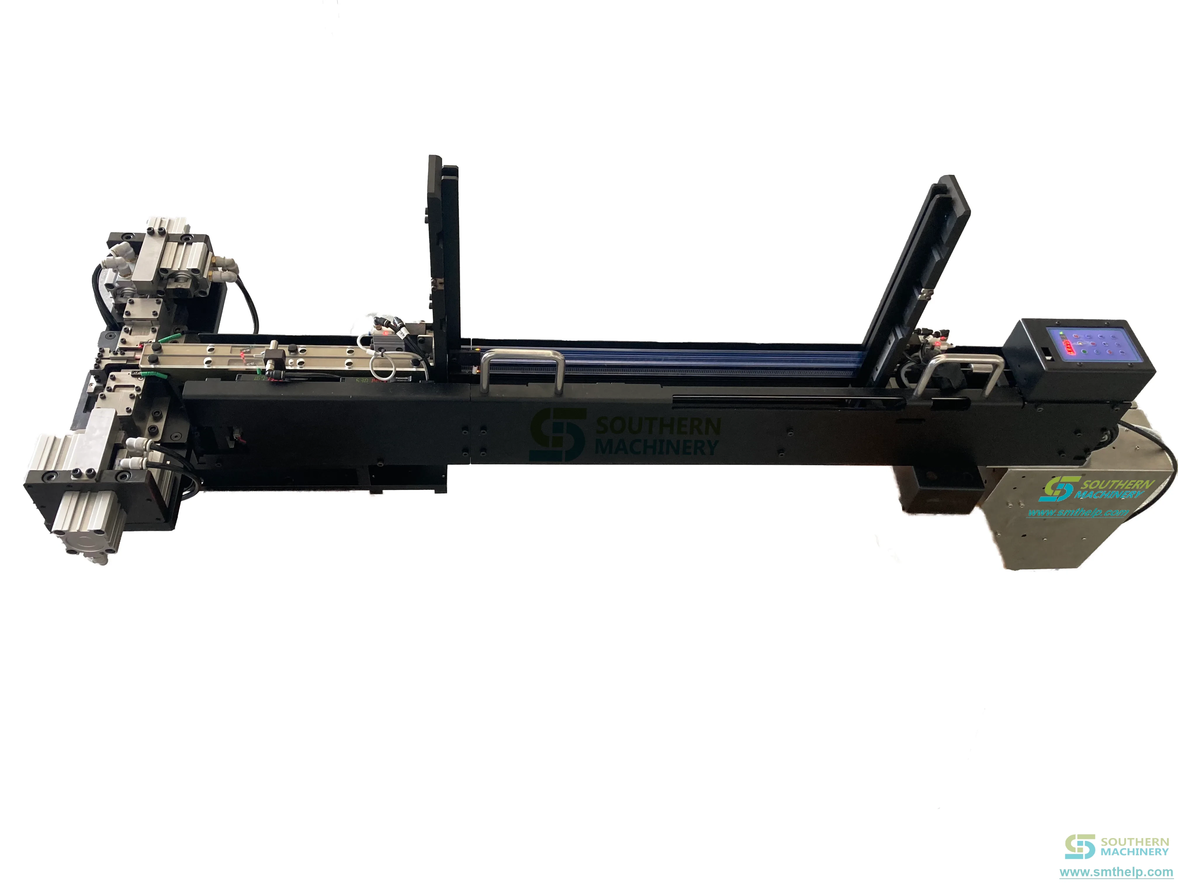
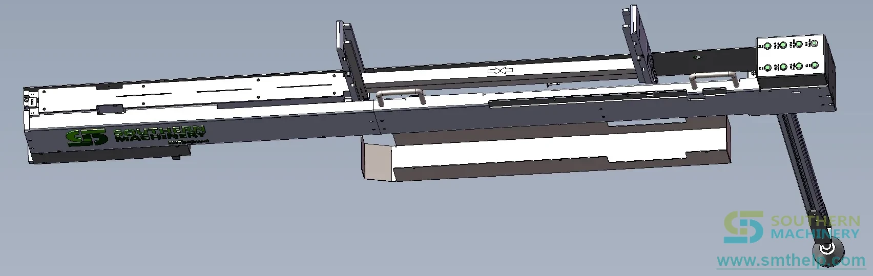
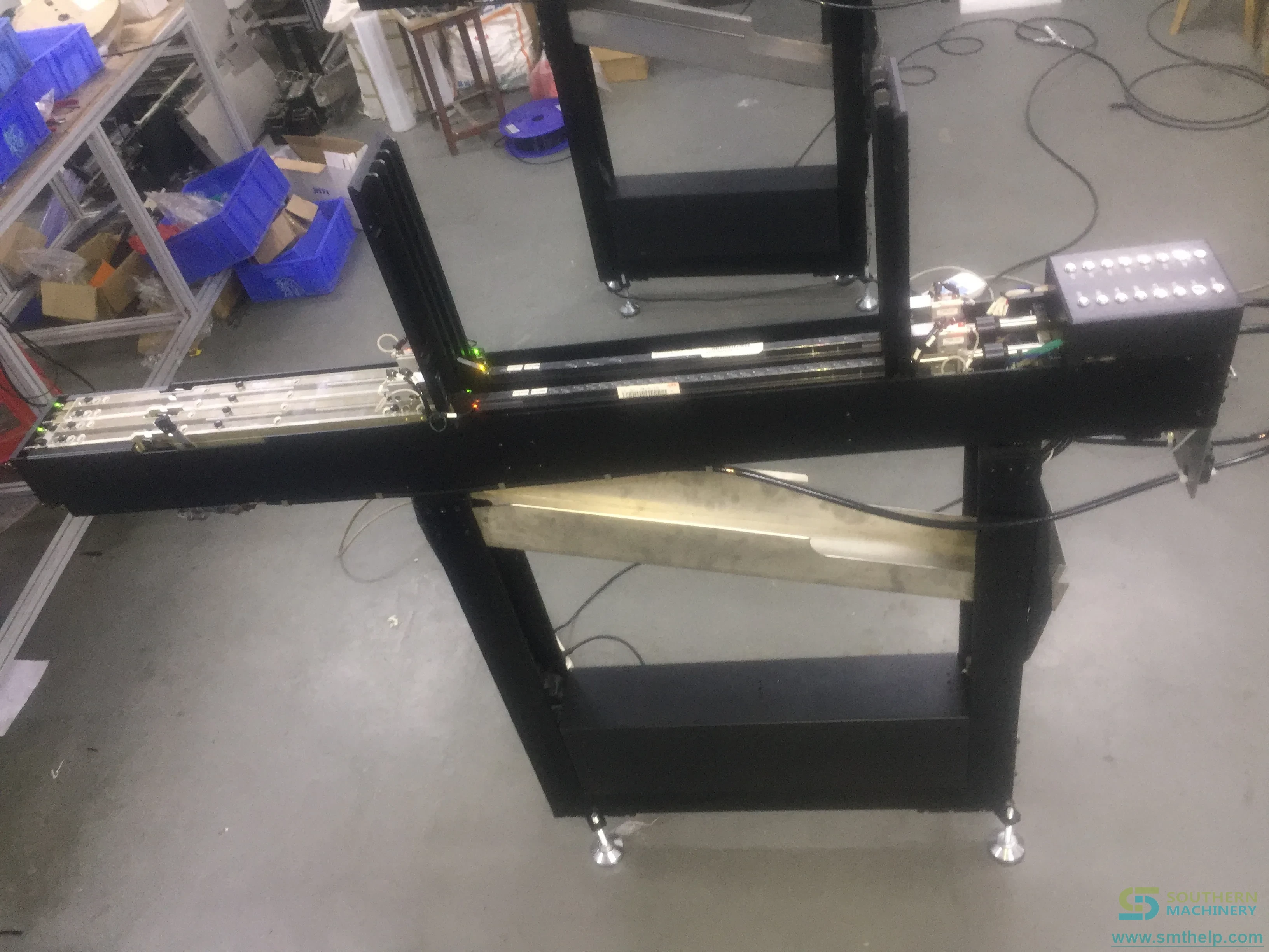
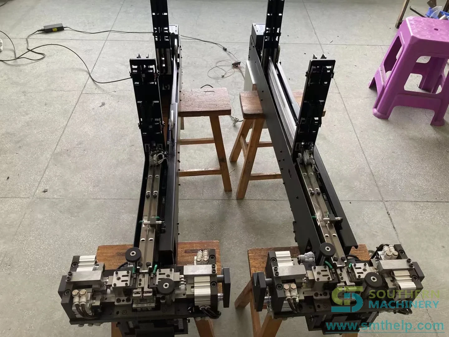
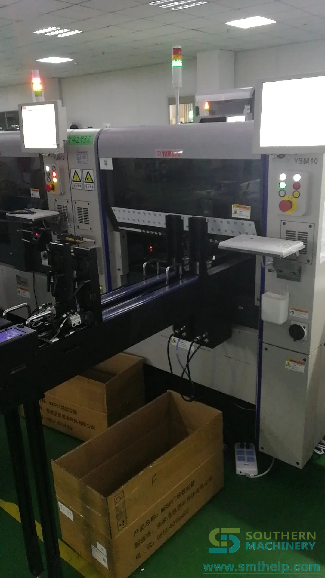
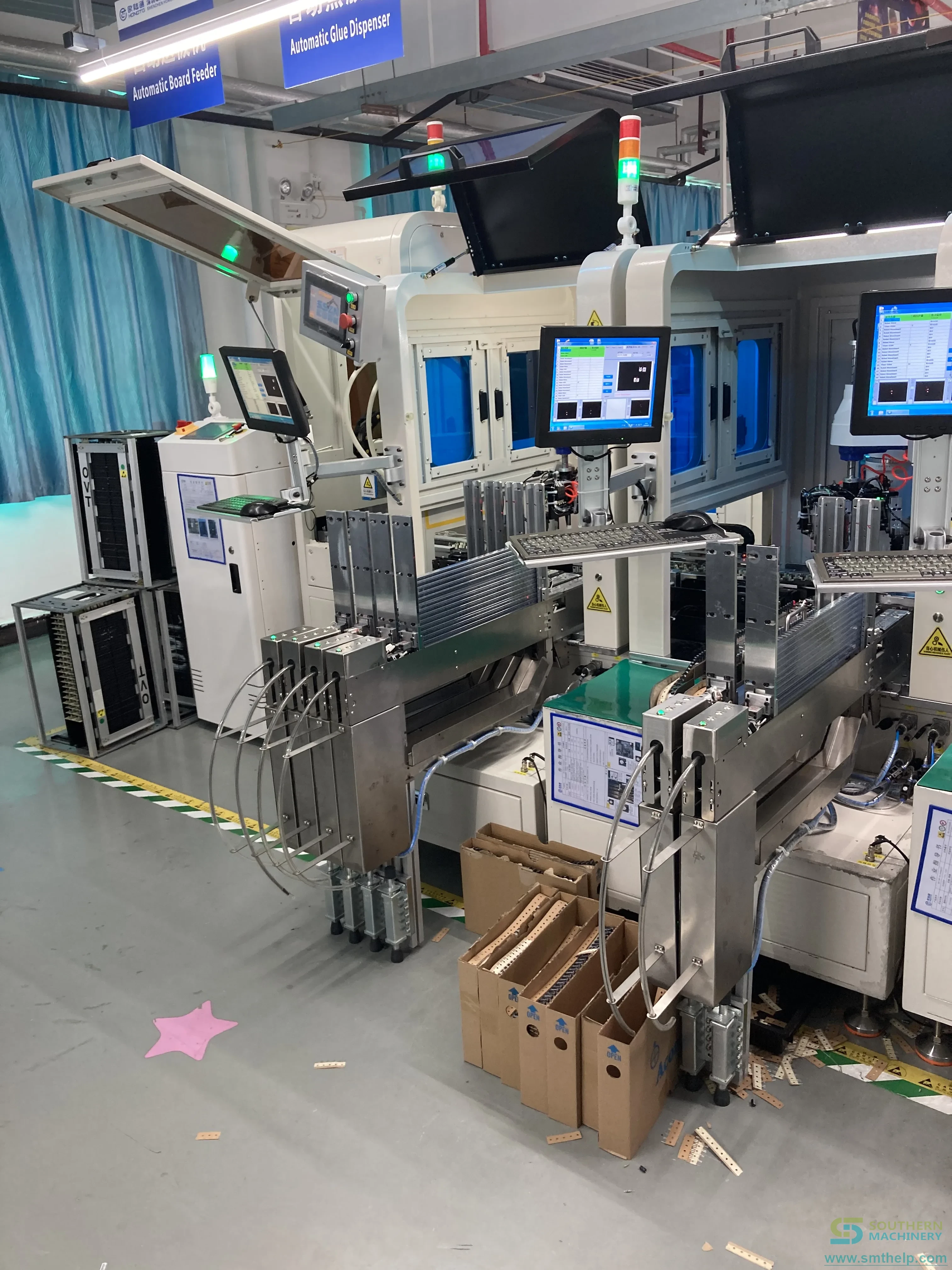
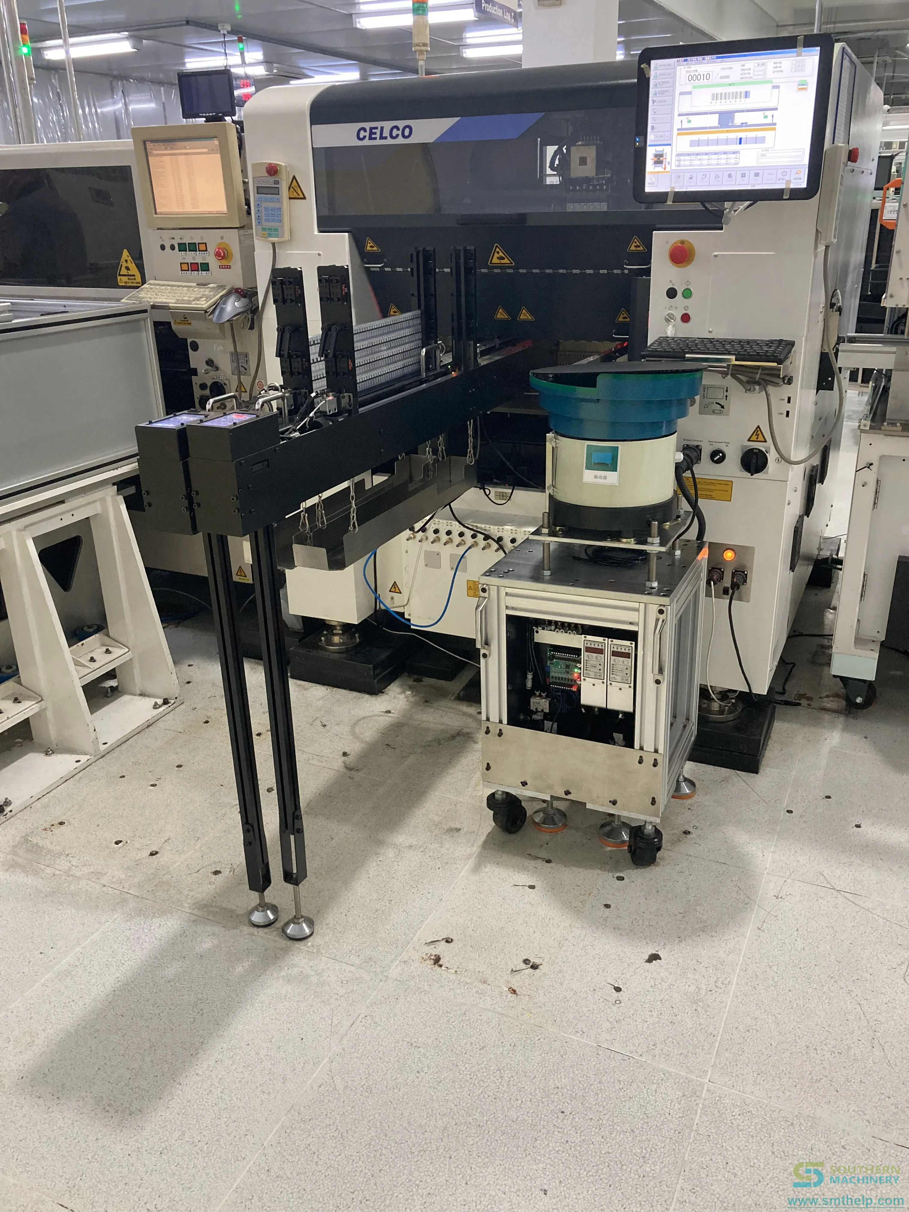
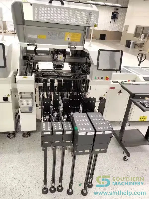
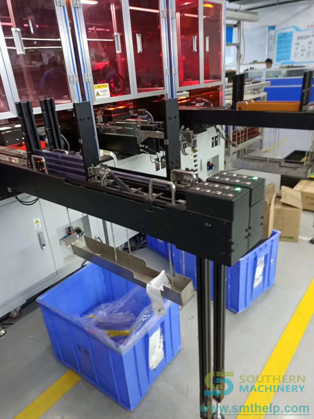
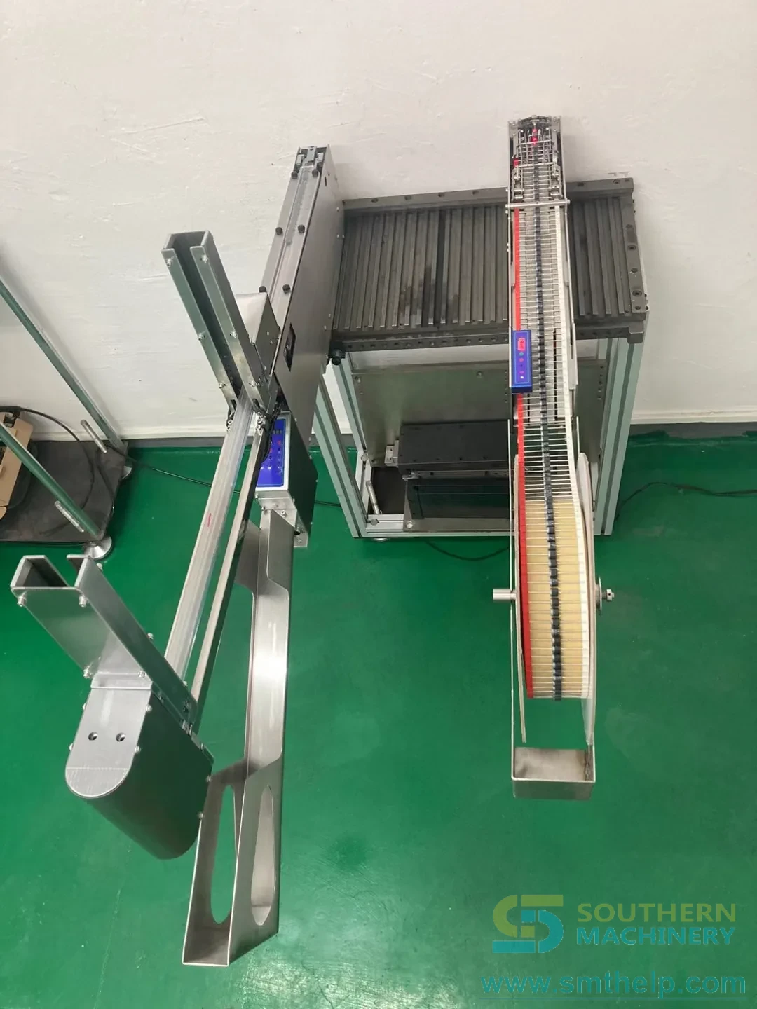
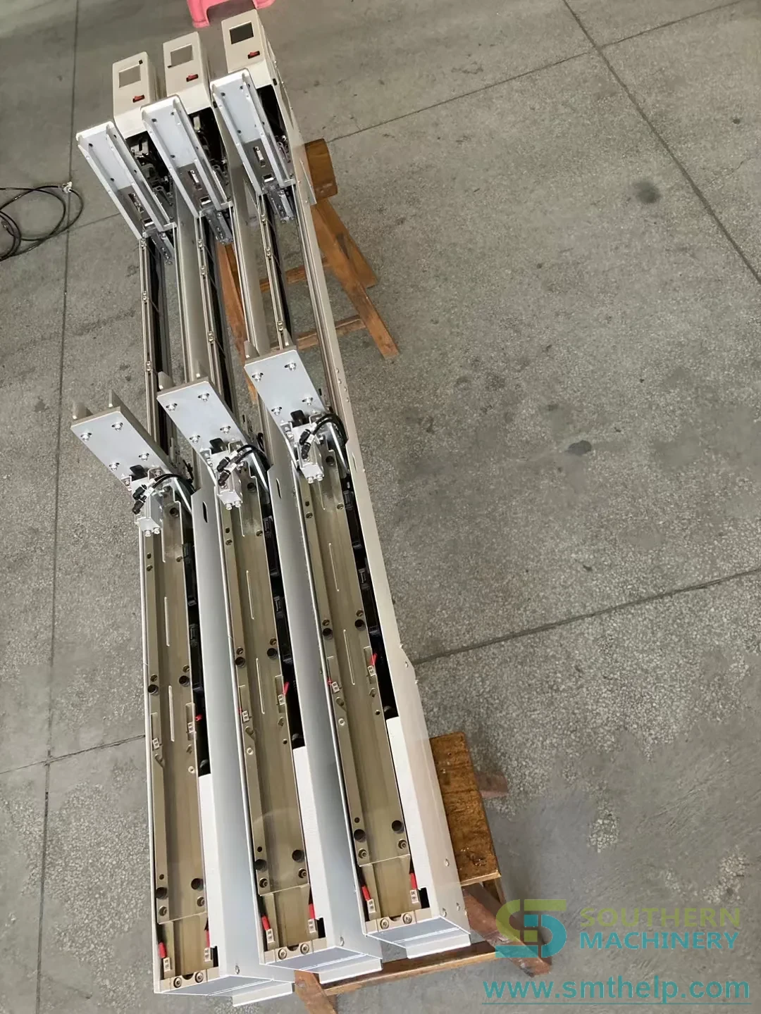
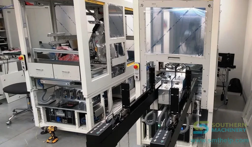
STF1003 tube feeder photographed against a plain background, stacked tube magazine on the left and control panel on the rightThree-dimensional render of the tube feeder showing its full length and the control box at the far endTube feeder on the factory floor with the track along the top and the recovery box underneathTwo complete tube feeders side by side on stands, both tube magazines raisedTube feeder installed on a YAMAHA placement machine with the feeder bank in the foreground
1350 x 92 x 115 mm
Footprint - it mounts in the feeder bank
3 x 3 x 3 - 25 x 25 x 25 mm
Component envelope handled
0.8 s
Published feeding speed per component
+/- 0.5 mm
Published feeding accuracy
Every value attributed to the document it came fromConflicting values disclosed side by side, not averagedUnconfirmed values marked To be confirmed
Why tube feeding

The stick is the packaging you already paid for

Relays, transformers, SOP chips and heavy terminals arrive in stick tubes because the tube protects the leads. That packaging is already bought and already on your dock. What is not free is the person who stands at the machine shaking parts out of it, one stick at a time.

01

The labour is the cost, not the tube

Tube-mounted odd-form parts are usually placed by hand or with a stick feeder an operator has to keep reloading. Every stick that runs out is a machine stop, and every stop is paid for at the line rate rather than the operator's rate.

02

A stacked magazine keeps the machine fed

The magazine holds several tubes at once. The manual documents a tube-change groove sensor, upper and lower tube sensors, and two air cylinders that seat the next tube and clear the empty one into a recovery box at the bottom.

03

One feeder across several part families

The sheet covers relays, terminals, transformers, square capacitors and round capacitors in a single envelope from 3 x 3 x 3 mm to 25 x 25 x 25 mm, so a changeover is a tube and a track adjustment rather than a second feeder.

How it feeds

From a stack of full sticks to an oriented part at the pick point

The mechanism is a stack, a spring and a track. A cylinder releases one tube out of the magazine, a second cylinder seats it against the track, and a motor-driven spring pushes the leading component out of the tube and along the track until a fibre sensor says it has arrived.

The STF1003 photographed against a plain background, with the stacked tube magazine on the left and the control panel on the right
Three-dimensional render of the feeder, showing the 1350 mm length and the control box at the far end
01

Load the stack

Full tubes go into the magazine. Orientation is set by the tube, so the operator does not have to present parts one by one.

02

Release one tube

The lower air cylinder drops a single tube out of the stack and into the feed position.

03

Seat the tube

The upper and lower managed cylinders clamp the tube against the track, so it cannot shift while the spring is pushing.

04

Spring push

A motor-driven spring runs inside the tube and pushes the leading component out of the open end.

05

Track transfer

The component travels along the track to the front of the feeder. Positioning is optical fibre sensing plus software compensation.

06

Front and mid sensing

Two fibre sensors watch the front end and the middle section, and the amplifier thresholds are set with the plus and minus keys.

07

Present at the pick point

The component is held at the front of the track and the feeder asserts component-in-position on pin 4 so the machine can pick.

08

Clear the empty tube

The empty tube is released, the cylinder swings clear of it, and it drops into the recovery box at the bottom of the feeder.

09

Change tube and repeat

A tube-change groove sensor confirms the swap and the cycle restarts. The published record is 1000 consecutive feeds, then 48 hours of ageing.

Sequence assembled from the operation manual's installation, operation and adjustment chapters and from the product sheet's feeding-method and drive rows. Cylinder travel and track geometry are configuration dependent.

LOAD
PUSH
PRESENT
Load the stack - release one tube - spring push - present at the pick point
Platform fit

Three things decide whether it drops into your line

A feeder is only useful if it mounts, if it can talk to the machine, and if it holds the part long enough for the nozzle to take it. Each of those is a documented feature here, and each one has a photograph behind it.

Source: STF1003 product sheet, the operation manual, and the Southern Machinery image library
Success case

Odd-form machines from four builders

The product sheet lists installations on Panasonic CM602, JUKI, YAMAHA and Mirae odd-form machines, in each case working alongside bowl feeders and radial tape feeders on the same platform.

Integration

SMT mounters, non-standard equipment, robot cells

The sheet states the feeder automates tube-mounted components - DIPs and transistors among them - for SMT machines, for non-standard equipment and for robotic arm integration. It is not restricted to one machine family.

Interface

Two ways to talk to the host

IO communication over the 8-core 16 mm aviation plug, where pin 4 carries the component-in-position signal, or self-control with no host link at all when the machine has no spare feeder interface.

Specification

Specification with sources

All 32 rows are reproduced from the supplied documents and each row names the document it was read from. Where a document does not state a parameter, the row says so rather than borrowing a value from another model.

Source: STF1003 product sheet (2025-10-07) and Stacked Tube Feeder Operation Instruction (20180901A03)
Parameter Specification Document it was read from What it means on the line
Model codeSTF1003Product sheet and catalogueThe code the product sheet, the feeder catalogue and the YouTube board all use.
Machine typeStacked tube feeder for SMT mounters and non-standard equipmentProduct sheetIt is built for tube-mounted parts, not for tape or tray reels.
Overall dimensions (L x W x H)1350 x 92 x 115 mmProduct sheet92 mm wide, so it occupies one feeder slot rather than floor space.
Weight25 kgProduct sheetOne person can lift it; no crane or trolley is needed for a swap.
Material typesRelays, terminals, transformers, square capacitors, round capacitorsProduct sheetHeavy leaded odd-form parts, which is what stick packaging is normally used for.
Material size3 x 3 x 3 mm to 25 x 25 x 25 mmProduct sheetCovers small SOP chips through to large transformers in one feeder.
Tube types acceptedPVC tubes, aluminium tubesProduct sheetBoth the cheap PVC stick and the aluminium stick are handled.
Tube length accepted200 - 650 mmProduct sheetCovers the common stick lengths. The manual quotes a narrower window - see open points.
Tube wall thickness0.6 mm or moreProduct sheetThin-wall sticks deform under the clamp and are not recommended.
Tube cross-section accepted6 x 10 mm minimum, 30 x 30 mm maximumOperation manual, chapter 1Stated in the manual only; the product sheet does not give it.
Feeding methodTube-fed material, multiple tubes stackedProduct sheetThe stack is what removes the reload stop from the operator's job.
Feeding powerMotor-driven springProduct sheetA spring runs inside the tube, so nothing has to grip the component body.
Material positioningOptical fibre sensing + software compensationProduct sheetThe stop position is corrected in software, not by moving a hard stop.
Fixing methodPositioning key + pressing block, other fixing structures supportedProduct sheetIt keys into the feeder plate, so it repeats position after a removal.
Tube exit handlingAir-cylinder avoidance, recovery box at the bottomProduct sheetEmpty tubes are collected rather than scattered on the floor.
Working voltage24 VProduct sheet and operation manualDC 24 V on both documents. The manual warns that over-voltage burns the control board.
Average current / peak current4 A / 6 AProduct sheetBudget a 24 V supply that can hold 6 A on inrush, not just the 4 A average.
Working air pressure0.4 - 0.6 MPaProduct sheetThe manual asks for more than 0.6 MPa. See open points before you set the regulator.
Operation modeButton operationProduct sheetStart, stop, motor reset, motor inching, and the two cylinder buttons on the panel.
Upper computer connection8-core 16 mm aviation plugProduct sheetA standard industrial plug, so a spare cable is easy to source locally.
Communication modeIO communication, or self-control with no communicationProduct sheetIt can run standalone when the mounter has no spare feeder interface.
Software controlBased on ARM (STC32)Product sheetA general-purpose 32-bit MCU, not a proprietary locked board.
Drive modeStepping motorProduct sheetStepping gives repeatable spring travel, which is what the accuracy figure depends on.
Motor type57-typeProduct sheetA common frame size, so the motor and its driver are not single-source.
Maximum motor speed600 rpmProduct sheetThe ceiling, not the running speed. Four speed gears sit below it.
Feeding speed0.8 sProduct sheetPer component, single channel. The throughput table turns this into an hourly figure.
Feeding channelSingle channel, dual channel can be customizedProduct sheetSingle channel is the standard; ask for dual if two part numbers run together.
Speed gearFour-gear adjustableProduct sheetFour discrete settings rather than a trim pot, so a setting can be written down.
Feeding accuracy+/- 0.5 mmProduct sheetTighter than the nozzle clearance on most odd-form heads, so the pick is repeatable.
Detection record1000 consecutive feeds without abnormalityProduct sheetThe published acceptance run. Ask for it to be repeated on your own part.
Ageing record48 hours of continuous operation without abnormalityProduct sheetA two-day continuous run, which is the closest published figure to a shift pattern.
Spring service life4 million bending cyclesProduct sheetThe spring is the wear part. At one cycle per component this is the number that sets the spare-parts interval.

Where the product sheet and the manual disagree

Two parameters are stated differently in the 2025 product sheet and the operation manual, and two more are stated in the manual only. They are reproduced in the open-points table above rather than resolved here.

Open points

Where the documents disagree, both values stay on the page

A specification table that quietly picks one of two numbers is worth less than one that shows both. Seven parameters below do not agree across the supplied documents, or are stated in only one of them. Five of the seven are explained by a different model or an older note; two are genuinely unresolved. Confirm the two before you place an order.

Status: two parameters to be confirmed, five clarified by source
Parameter Product sheet and catalogue, 2025 Operation manual 2018, and earlier notes What the difference means Status
Working air pressureWorking air pressure 0.4 - 0.6 MPa.Air pressure above 0.6 MPa, and it states that below 0.6 MPa the component will not reach the correct position.The sheet gives a band that ends where the manual's floor begins. Set the regulator to the higher figure until your own drawing settles it.To be confirmed
Tube length acceptedTube length 200 - 650 mm.Tube size minimum 300 x 6 x 10 mm and maximum 600 x 30 x 30 mm.The manual's window is narrower at both ends. A 250 mm or 640 mm stick is inside the sheet's range and outside the manual's.To be confirmed
Working voltageWorking voltage 24 V; the manual states DC 24 V.A 2021 product note for the same feeder states a 100 / 220 V supply.24 V is the feeder's own working voltage on both the 2025 sheet and the 2018 manual. The 2021 figure is most likely the host supply or an earlier design - do not wire 220 V to the feeder on the strength of it.Clarified by source
Feeder dimensions1350 x 92 x 115 mm.A 2021 product note prints 135 x 92 x 115 mm. The STF-1002 stacked tube feeder is a separate, larger machine at 1460 x 80 x 1148 mm with a 40-tube magazine.The 2021 figure is the 2025 figure with a digit lost in transcription, and the numbers that follow it in that note (25 kg, 200 - 650 mm, 0.8 s) confirm which machine it describes. The STF-1002 is a different product - do not order against its dimensions.Clarified by source
Drive and motorFeeding power is a motor-driven spring; the drive is a 57-type stepping motor at 600 rpm maximum.The SSTF01 SOP tube feeder sheet - a different product - states motor-driven belt feeding with a DC motor at 300 rev / min.Two members of the tube-feeder family with different drive trains. The SSTF01 figures describe the SOP belt machine and do not apply to the STF1003.Clarified by source
Speed adjustmentSpeed gear: four-gear adjustable.The SSTF01 sheet states infinitely variable.Different control implementations on the two models, not two descriptions of one machine. Four gears is what the STF1003 sheet says.Clarified by source
Component familiesRelays, terminals, transformers, square capacitors and round capacitors, 3 x 3 x 3 mm to 25 x 25 x 25 mm.The SSTF01 sheet lists SOP chips, MOS tubes and heat sinks.The two sheets address different part families. Send a sample of your part and the answer is settled on the machine rather than on a datasheet.Clarified by source

This page is not a quotation. Values are reproduced from the documents named in each row; the current drawing for your configuration governs. Nothing here has been averaged, interpolated or carried across from another model.

Throughput

What a single channel is worth per hour

The feeder is single channel, so the upper bound is set by the published 0.8 s feeding speed. The table converts that speed, and two slower settings, into components per hour at three realistic availability levels.

Derived from the published 0.8 s feeding speed
Feeding speedTheoretical components/hourAt 90 percent availabilityAt 80 percent availability
0.8 s450040503600
1.0 s360032402880
1.2 s300027002400

Derived arithmetic, not a measured production figure. It counts components, not finished boards: the machine cycle, the number of tube-fed parts per board and the operator's refill interval all sit on top of it. A stacked magazine is what keeps the refill interval from becoming the real limit.

Configuration

What you choose when you order

Each of these is a documented feature of the platform rather than a custom engineering project.

Source: STF1003 product sheet and the Stacked Tube Feeder operation manual

Dual-channel feeding

Single channel is the standard. The sheet lists dual-channel feeding as a customization for lines that run two tube part numbers together.

Recovery box for empty tubes

Empty tubes are cleared by air cylinder and collected in a box at the bottom of the feeder, so the stack does not have to be hand-sorted at the end of a shift.

Tube-change sensing

The manual's IO table carries a dedicated tube-change groove switch plus upper and lower tube sensors, so the swap is detected rather than assumed.

Spring and wear parts

The motor-driven spring is rated at 4 million bending cycles. It is the part that sets the service interval, and it is replaceable.

Host interface

8-core 16 mm aviation plug carrying the component-in-position signal on pin 4, or self-control with no host link.

Mounting for non-standard equipment

Positioning key plus pressing block, with other fixing structures supported for a machine that has no standard feeder plate.

Commissioning

Six steps from crate to first accepted component

The manual describes the machine as a sequence: mount, air, power, load, adjust, prove. These are the six stations in that order, with the manual's own warnings kept where they belong.

STEP 1

Mount and clamp

Align the pin holes, seat the positioning key in the plate slot and pull the clip tight. The rear positioning pin stops left and right yaw.

STEP 2

Air on

The manual asks for more than 0.6 MPa and warns that below it the component will not reach position. The product sheet gives a 0.4 - 0.6 MPa band - set to the higher figure until your drawing settles it.

STEP 3

Power on

DC 24 V. Pin 1 is 24 V and pin 2 is GND. The manual is explicit: connect 24 V first, then the air supply, and never short 24 V to 0 V.

STEP 4

Load the stack

Put full tubes into the magazine, then press start until the running light goes green. The manual's warning: never let the spring push air - the spring must have a component or a tube in front of it or it will bend.

STEP 5

Tune the sensors

Fibre amplifier thresholds with the plus and minus keys, then the upper and lower cylinder positions, then the baffle width if empty tubes do not fall freely.

STEP 6

Prove it

Run 1000 consecutive feeds, then a 48-hour ageing run. Those are the published acceptance figures, and they are worth repeating on your own component.

1350 x 92 x 115 mm 25 kg DC 24 V 0.4 - 0.6 MPa +/- 0.5 mm 0.8 s per component

Installation is a qualified task. The manual assumes the machine is de-energised and the air supply isolated before any panel is opened, and it asks for the fibre heads to be cleaned with alcohol on a regular schedule to keep dust out of the sensing.

Payback

Work out the payback from your own numbers

Nothing on this page asserts a saving. The two machine values are the published feeding speed and the component count you enter; everything else is yours to set. If the machine time is not shorter than the manual time, the page says so instead of printing a negative.

Tube feeding payback

Enter your own labour rate and tube part mix

Machine time per board
— s
Handling hours released
— h / month
Labour released
— USD / year
Payback
—
Illustrative model, not a quotation. Machine time uses the published 0.8 s feeding speed. The model ignores the tube and packaging cost, quality yield and machine utilisation, all of which affect the real answer. It also assumes the magazine keeps the feeder loaded, which is the whole point of a stacked design.
Working video

The feeder running

Selected from the Southern Machinery YouTube board. Titles and running times are the board's own, not re-worded here, and where a clip shows a different model the caption says which.

Insights

Eight notes on feeding parts that arrive in sticks

Long-form notes on tube feeding, written for process engineers and production managers who have to make the decision, not just read about it.

ARTICLE 01Tube-Mounted Parts Are a Labour Problem Wearing a Packaging Costume

The stick looks free because it arrived with the part. The person holding it is not.

Full articles are in English. The summary above carries the argument in your language.

A production manager walks the line and sees a person at the odd-form station holding a stick tube, tilting it, waiting for a part to slide down, and picking it with tweezers. The manager notes 'odd-form insertion - 1 operator' on the headcount sheet and moves on. That single line is where most tube-feeder business cases are lost, because it records a person without recording what the person is doing.

What the person is doing is not insertion. Insertion is the machine's job. What the person is doing is packaging removal, orientation and presentation - three steps that only exist because the part arrived in a stick. If the same part arrived on tape, none of those three steps would be on the headcount sheet at all; they would be inside the feeder, invisible, and nobody would be counting them.

The stick is genuinely good packaging. It protects long leads, it stacks and ships cheaply, and for heavy transformers and relays it is often the only packaging that survives a container. The mistake is not the packaging. The mistake is treating the packaging as free once it has arrived, when in fact every stick that reaches the line carries a handling cost that has simply been booked to a different account.

Count it directly. Time one stick end to end: the walk to the store, the walk back, opening the end plug, presenting parts until the stick empties, dealing with the last two that will not slide, and the seconds lost each time the machine waits. Multiply by the number of sticks a shift consumes. That number, divided by the number of good boards produced in the shift, is the handling cost per board. It is almost always larger than the part-cost difference that made the purchasing team choose this supplier.

What changes with a tube feeder is not the packaging but the accounting. The stick still arrives; it now goes into a magazine instead of a hand. A stacked magazine holds several tubes, and the changeover from an empty tube to the next full one is done by air cylinders and detected by a groove sensor rather than by an operator noticing. The handling cost does not go to zero - someone still loads the magazine - but it stops scaling with the number of parts placed.

The practical test is to watch the station for one hour and write down every action that would not exist if the parts arrived already oriented at the pick point. If that list is longer than the list of actions the machine performs, the labour is the problem and the packaging is only the costume it is wearing. That is the point at which a tube feeder becomes a labour decision rather than a capital decision.

ARTICLE 02What Manual Stick Placement Really Costs on a 300-Board Day

A four-line calculation that turns stick handling into a number a finance team will accept.

Full articles are in English. The summary above carries the argument in your language.

Numbers persuade finance teams; adjectives do not. So here is a four-line calculation that turns stick handling into a figure that survives a review, using a 300-board day as the example.

Line one: components per board. Take the tube-fed part numbers on the BOM and count how many of them a board actually uses. On a typical power board this is somewhere between eight and twenty; on a control board with several relays it can be higher. Call it twelve, and be honest - if it is thirty, use thirty.

Line two: seconds of manual handling per component. This is the number people guess at, and it is the one worth measuring. Stopwatch one stick: from picking it up to putting the empty stick down, including the parts that refuse to slide. Divide by the number of components in the stick. Typical answers land between fifteen and thirty seconds. Use twenty.

Line three: the machine's own time per component. This is the one figure that comes from a document rather than a stopwatch. The STF1003 product sheet states a feeding speed of 0.8 seconds per component, single channel. Twelve components is therefore 9.6 seconds of feeder time per board, against 240 seconds of manual time.

Line four: the monthly difference. Twelve components times the 20 second manual time, minus the 9.6 seconds of feeder time, is 230.4 seconds released per board. At 300 boards a day and 26 days, that is 7,800 boards a month, or 499 handling hours a month. At a fully loaded rate of 700 USD a month per operator, releasing one operator is 8,400 USD a year. Against a machine investment you supply yourself, the payback falls out of the division.

Three warnings about this arithmetic. It counts handling only - it ignores yield, rework and the quality cost of hand-placed parts, all of which favour the machine. It assumes the magazine keeps the feeder loaded, which is exactly what a stacked design is for; a single-tube feeder would spend part of every hour waiting for a person instead. And it assumes the released time is actually used. Releasing an hour is not the same as removing a cost, and the difference is a management decision rather than an engineering one.

ARTICLE 03How to Tell Whether a Part Belongs in a Tube Feeder

Four checks you can run on a sample stick before anyone quotes you a machine.

Full articles are in English. The summary above carries the argument in your language.

Not every part belongs in a tube feeder, and the fastest way to damage a feeder project is to convert a part that should have stayed on tape. Four checks on a sample stick will tell you most of what you need to know before anyone quotes a machine.

Check one: does the part slide? Hold the stick at a shallow angle and let gravity do the work. A part that needs shaking, tapping or a steep tilt is a part that will need a spring pushing it, and even then the friction that stops it sliding will be the friction that wears the tube. Slide freely at a low angle, or plan for a fight.

Check two: does the part have a feature the feeder can reference? The STF1003 positions by optical fibre sensing with software compensation, so it does not need a hard stop, but it does need a consistent silhouette. A part whose outline changes every time it presents - because a lead is bent, because a plastic body has a flash line, because the marking faces a different way - will give the sensor an inconsistent edge.

Check three: do the leads survive the journey? A tube feeder pushes parts along a track and out of a tube end. Long, soft or pre-formed leads are the parts that arrive at the pick point already out of tolerance. The product sheet's envelope runs from 3 x 3 x 3 mm to 25 x 25 x 25 mm, which covers heavy transformers and relays as well as small SOP chips, but the envelope says nothing about whether the leads can take the handling.

Check four: does the tube itself behave? The sheet gives a tube length of 200 to 650 mm and a wall thickness of 0.6 mm or more, in PVC or aluminium. The manual gives a narrower window, 300 to 600 mm long and 6 x 10 mm to 30 x 30 mm in cross-section. Thin-wall PVC deforms under the clamp; a stick with a rough internal seam will jam a part that slid perfectly in a smooth one. Squeeze the tube and watch what happens.

If the part passes all four, a tube feeder is worth quoting. If it fails one, the failure usually has a fix: a different tube, a different track, a dual-channel configuration. If it fails two, send the sample anyway and let it be tested on the machine - but expect the answer to be no, and plan the alternative before the budget is committed.

ARTICLE 04Six Checks Before You Take SOP Chips Off Manual Placement

A short acceptance routine that stops a tube-feeder conversion failing on the line.

Full articles are in English. The summary above carries the argument in your language.

A conversion that works on the bench and fails on the line usually fails for a reason that was visible before the order was placed. Six checks, run in this order, catch most of them.

Check one: the acceptance run. The product sheet states 1000 consecutive feeds without abnormality, followed by 48 hours of continuous ageing, and a spring rated at 4 million bending cycles. Insist that the run is repeated on your own component rather than accepting the catalogue figure. A feeder that feeds a demo part perfectly and your part badly has told you something useful about your part.

Check two: the accuracy budget. The published feeding accuracy is plus or minus 0.5 mm. Add that to the placement head's own repeatability and compare the total with the lead-to-hole clearance on the board. If the sum is larger than the clearance, the problem is not the feeder and no amount of feeder tuning will fix it.

Check three: the tube, not the part. The sheet accepts PVC and aluminium tubes from 200 to 650 mm with a wall of 0.6 mm or more; the manual narrows that to 300 to 600 mm. Measure the sticks you actually buy, from the supplier you actually use, and check them against the narrower window, because that is the one the person commissioning the machine will be reading.

Check four: the air supply. This is the one parameter where the supplied documents genuinely disagree: the product sheet gives 0.4 to 0.6 MPa, the manual asks for more than 0.6 MPa and states that below that the component will not reach position. Measure the pressure at the feeder, not at the compressor, and remember that the manual's warning is about position, not about the cylinder failing to move at all.

Check five: the electrical interface. The feeder runs on DC 24 V with an average current of 4 A and a peak of 6 A, and connects through an 8-core 16 mm aviation plug with the component-in-position signal on pin 4. It can also run self-controlled with no communication at all. Decide which mode you are buying before the electrician arrives, because the two need different cable work.

Check six: the person who will own it. Someone has to load the magazine, set the four speed gears, adjust the fibre thresholds and clean the fibre heads with alcohol. The manual documents all of it, but documentation is not ownership. Name the person before the machine is ordered, and the first month of running will cost a fraction of what it costs otherwise.

ARTICLE 05The Stacked Magazine Is the Feature That Actually Buys You Throughput

Feeding speed gets the attention. Tube changeover is what decides the shift.

Full articles are in English. The summary above carries the argument in your language.

Feeder specifications are usually compared on feeding speed, and feeding speed is the least interesting number on the sheet. A feeder that presents a component in 0.8 seconds and then stops because the tube is empty is slower in production than one that presents in 1.2 seconds and never stops.

Work the arithmetic. At 0.8 seconds per component the theoretical ceiling is 4,500 components an hour. If a tube holds thirty components and the operator takes ninety seconds to notice an empty tube, fetch a new one, open it and load it, then every thirty components costs ninety seconds of machine time. That is three seconds per component added to the 0.8, and the effective rate drops by three quarters before a single board is produced.

The stacked magazine attacks exactly this number. Several tubes sit in the magazine at once, so the changeover from empty to full happens inside the machine's own cycle. The operation manual documents the mechanism in detail: a lower air cylinder drops a tube into the feed position, an upper cylinder seats it against the track, and after the tube empties a cylinder swings clear so the empty tube falls into a recovery box at the bottom. The manual's IO list carries a dedicated tube-change groove switch and separate upper and lower tube sensors, which is what makes the swap detected rather than assumed.

That changes what the operator's job is. Instead of responding to a stop, the operator tops the magazine up when it gets low. The difference in the labour model is the difference between a person who is tied to a machine and a person who visits it - and only the second one can be given another station.

It also changes the failure mode. An empty tube in a single-tube feeder is a machine stop. An empty magazine is a warning. The published figures support the mechanism rather than the marketing: 1000 consecutive feeds without abnormality, 48 hours of continuous ageing, and a spring rated at 4 million bending cycles, which at one cycle per component is a very long interval between spring changes.

So when you compare tube feeders, ask three questions in this order. How many tubes does the magazine hold? What detects the changeover, and is it a sensor or an assumption? And what happens to the empty tube - is it collected, or does it end up on the floor next to the machine? The answers tell you more about your hourly rate than the feeding speed does.

ARTICLE 06Setting Up a Tube Feeder: The Five Adjustments That Decide Everything

Two fibre thresholds, two cylinder positions and one baffle width. Everything else is a consequence.

Full articles are in English. The summary above carries the argument in your language.

A tube feeder is not difficult to set up, but it is easy to set up in a way that works for a week and then drifts. The operation manual describes a long adjustment chapter; five of those adjustments are the ones that decide whether the feeder runs or fights you.

Adjustment one and two: the two fibre thresholds. The manual's method is simple and worth following exactly. When the component is in the right position and the lamp does not light, raise the threshold with the plus key. When the component has been picked and the amplifier indicator has not gone out, lower it with the minus key. Do this for the front-end fibre and again for the mid-section fibre. Because positioning is optical fibre sensing with software compensation, the threshold is the calibration - there is no mechanical stop to move.

Adjustment three: the upper and lower cylinder positions. If components jam when they enter the tube line, the bottom cylinder goes up or down. If the cylinder fails to push the component, the upper and lower positions of the prop cylinder are adjusted slightly. These two cylinders are what seat the tube against the track, and a tube that is seated a fraction high will present the component a fraction high.

Adjustment four: the baffle width. When an empty tube does not fall freely, the manual says to widen the left and right baffles slightly. This is the adjustment people skip, and it is the one that produces the intermittent fault that nobody can reproduce - the empty tube that hangs for a second before dropping, and the sensor that reads it as still present.

Adjustment five: the sensor positions for tube presence. The manual gives two cases. When there is a tube at the bottom and another tube keeps falling out instead of the bar drawing back, adjust the sensor so it lights on the correct tube position. And when there are many tubes at the back-end charging place but each feed spring still pushes to the bottom, adjust the position of the sensor so that it lights when a tube is above. Both cases are the same mistake: the sensor is reading the position next to the one you think it is reading.

The order matters. Fibres first, because they define what 'in position' means. Cylinders second, because they define where the component is. Baffles third, because they only affect empty-tube handling. Sensors last, because they are the only adjustment that depends on all three of the others being right. Run them in that order and the setup survives a shift change; run them in any other order and you will be back at the machine on Friday.

ARTICLE 07Keeping a Tube Feeder Running: The Sensor Checks That Prevent Most Stops

The manual's fault table, turned into a checklist a shift leader can actually own.

Full articles are in English. The summary above carries the argument in your language.

The operation manual's fault-treatment chapter is a list of symptoms, and read carefully it is also a maintenance schedule. Almost every fault it describes is a sensor or a valve reporting something other than the truth, and almost all of them announce themselves before they stop the line.

Start with the fibre amplifier. The manual's first entry covers the front-end and mid-section fibres. If the amplifier is permanently on, or comes on and off without a component present, the fault will show up as either the material reaching the feed position but the spring never returning, or the front position being empty while the spring never pushes. The manual's fix is to re-run the 5-1 adjustment method, and only then to replace the amplifier. Cleaning the fibre heads with alcohol on a regular schedule, which the manual asks for explicitly, prevents a large share of these.

Then the tube sensors. The manual gives the symptoms in both directions. A failed lower sensor shows up as an empty tube that does not raise an alarm, a feed spring that keeps acting, or a tube-change operation that runs continuously. A failed upper sensor shows up as every tube being pushed to the bottom and tube changes running all the time. Both are one-part replacements, and both are much cheaper to do during a planned stop than during a shift.

Then the two switches on the spring. If the spring does not return to its origin position and keeps running backwards until it jams, the origin groove switch is the suspect. If the spring reaches its limit position and the motor does not stop, the limit groove switch is the suspect. These two protect the spring, and the spring is rated at 4 million bending cycles - so a switch that fails open costs a great deal more than the switch.

Then the air path. If the cylinder does not move in automatic mode, the manual's test is to press the cylinder up and down buttons in manual mode. No movement in manual mode points at the solenoid valve rather than at the control logic. And if the device powers on with no action at all, no panel response and no sensors lit, the manual's answer is the control board or the IO board - which is exactly why the manual warns so firmly against shorting 24 V to 0 V.

Turn that list into a checklist and give it to a shift leader. Fibre heads cleaned. Amplifier indicators behaving. Tube sensors responding to a known-empty and a known-full position. Spring origin and limit switches lighting when they should. Cylinder movement proven in manual mode at the start of each shift. Ten minutes, once a day, and most of the faults in the manual never reach the line.

ARTICLE 08Costing a Tube Feeder Without Guessing

Which numbers to insist on before you approve the spend, and which ones to ignore.

Full articles are in English. The summary above carries the argument in your language.

A tube-feeder proposal usually arrives with a price and a feeding speed, and the two numbers are not enough to make a decision. Here is what to insist on before the spend is approved, and what to ignore.

Insist on the acceptance run, on your part. The product sheet's published figures are 1000 consecutive feeds without abnormality and 48 hours of continuous ageing. Those are the manufacturer's numbers on a representative component. Your number is the same run on the component that actually causes trouble, and it should be a condition of the order rather than a promise made at the demonstration.

Insist on the tube specification in writing. The sheet accepts tubes from 200 to 650 mm with a wall of 0.6 mm or more in PVC or aluminium; the manual narrows the window to 300 to 600 mm and gives a cross-section range of 6 x 10 mm to 30 x 30 mm. Since the two supplied documents disagree, get the window confirmed against the sticks you actually buy before the order, not after.

Insist on the air figure. This is the second genuine disagreement: 0.4 to 0.6 MPa on the sheet against more than 0.6 MPa in the manual, with the manual warning that below 0.6 MPa the component will not reach position. A feeder installed on an under-sized air line will present parts slightly out of position, and the symptom will look like a feeder fault rather than an air fault.

Insist on the magazine size and the changeover behaviour. These are the numbers that decide your hourly rate, and they are not on the summary line of any quotation. Ask how many tubes the stack holds, what detects the changeover, and where the empty tube goes. The manual's answer on the last point is a recovery box at the bottom, cleared by air cylinder - if a supplier cannot answer these three questions, the specification is not finished.

Ignore, for now, the difference between 0.8 seconds and a competitor's faster figure. At twelve components a board the difference between 0.8 and 0.6 seconds is 2.4 seconds of machine time per board, which is real but small next to a single unplanned tube changeover. Ignore also any claim about yield that is not backed by a measured run. And ignore the unit price of the feeder until you have the handling hours from your own line - the payback is a ratio, and the denominator is the part you can actually measure.

Documents

Take the source documents with you

Every link below was opened and checked. The product sheet and the manual are the documents this page quotes.

STF1003 Tube Feeder product sheet

The sheet this page quotes for dimensions, weight, component envelope, feeding speed, accuracy and the test record.

Stacked Tube Feeder operation instruction

The full manual: basic parameters, spare parts list, installation, operation, adjustment, fault treatment and the IO list.

Feeder and nozzle catalogue V03

Southern Machinery customized feeder and nozzle catalogue - the whole feeder family on one document.

Related tube-feeder documents

The SSTF01 SOP tube feeder sheet, the S-JVF02 vibration stick feeder sheet, and the SMT stick tube feeder drawing. These describe other members of the family and are here for comparison.

Support

What happens after the feeder lands

Southern Machinery designs and manufactures in Shenzhen and supports the machines it ships.

✓

Component trial before you commit

Send a sample stick of the part. The feeder is proven against your actual component, not a catalogue photograph.

⚑

Tube and track setup for your part

Track position, cylinder travel and fibre thresholds are set for your tube and your component envelope.

⚙

Operator and maintenance training

Button states, the four speed gears, the two fibre channels and the cylinder adjustments are all covered in the manual.

Spares and consumables

Springs, tube sensors, groove switches, fibre amplifiers and the air cylinders are the wear items. The spring is rated at 4 million cycles.

FAQ

Questions buyers ask before the first sample

Which components can the STF1003 feed?
The product sheet lists relays, terminals, transformers, square capacitors and round capacitors, in a size envelope from 3 x 3 x 3 mm to 25 x 25 x 25 mm, and states that it automates tube-mounted parts including DIPs and transistors for SMT machines, non-standard equipment and robotic arm integration.
Which tube sizes does it accept?
The product sheet gives a tube length of 200 to 650 mm and a wall thickness of 0.6 mm or more, in PVC or aluminium. The operation manual gives a narrower window, 300 to 600 mm long and 6 x 10 mm to 30 x 30 mm in cross-section. That difference is listed in open points and is not yet confirmed.
Will it fit my machine?
The product sheet lists installations on Panasonic CM602, JUKI, YAMAHA and Mirae odd-form machines, and states high compatibility with SMT machines generally. It connects through an 8-core 16 mm aviation plug and can also run with no communication at all, so a machine without a spare feeder interface is not excluded.
How fast is it?
The published feeding speed is 0.8 seconds per component, single channel, with a 57-type stepping motor rated to 600 rpm and four selectable speed gears. The throughput table on this page turns 0.8 seconds into an hourly figure at three availability levels.
What air and power does it need?
DC 24 V, with an average current of 4 A and a peak of 6 A. Air is the one genuine conflict: the product sheet gives 0.4 to 0.6 MPa while the manual asks for more than 0.6 MPa and warns that below that the component will not reach position. Set the higher figure until your own drawing settles it.
How does tube changeover work?
The magazine holds several tubes. A lower air cylinder drops one tube into the feed position, an upper cylinder seats it, and after the tube empties a cylinder swings clear of it so it falls into the recovery box at the bottom. The manual's IO list carries a dedicated tube-change groove switch plus upper and lower tube sensors, so the swap is detected rather than assumed.
How accurate is the pick position?
The published feeding accuracy is plus or minus 0.5 mm, achieved by optical fibre sensing with software compensation rather than by a mechanical hard stop. Front-end and mid-section fibre sensors watch the component, and the amplifier thresholds are set with the plus and minus keys.
How do I know it will not jam on my part?
The published record is 1000 consecutive feeds without abnormality followed by 48 hours of continuous ageing, and the spring is rated at 4 million bending cycles. For a new part, send a sample stick and we will run the feeder against it rather than asking you to accept a catalogue claim.
Contact

Send the stick, not just the enquiry

The fastest answer is a sample stick and a photograph of the component. Tell us the part, the tube, the board and the volume and we will tell you whether it can be fed from a stack - including when the answer is no.

STF1003 tube feeder enquiry

This form opens your own mail client. Nothing is sent from the page.

Tell us the part number and the monthly volume

Send a sample stick of the component. We will confirm whether the STF1003 can present it to your placement machine, and what the changeover looks like when the part mix moves on.

Request a component trial