
Every machine value on this page is quoted from the S7020T Use's Manual, the S-7000T terminal insertion solution sheet or the S-7000 presentation · Each figure is traceable, and every disagreement between the three is published below
Southern Machinery Southern MachinerySmart EMS Factory Partner
THT terminal insertion · reel, bulk and radial-taped terminals

Your terminals go in one at a time.
This one places them 0.6 seconds apart.

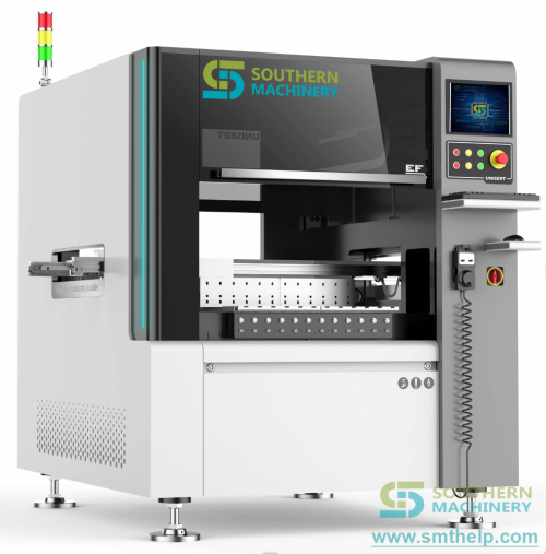
The S7020T is a vision-corrected THT insertion machine for tact switches, strip connectors, copper inserts and axial braided parts. It reads the PCB hole positions with a camera, corrects the offset automatically, then drives each terminal home and clinches it — inward, outward or in an N form. Tape feeder, bowl feeder or track: whatever packaging your terminal arrives in, there is a feed path for it.

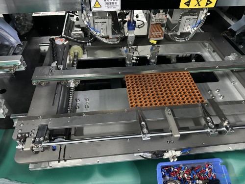
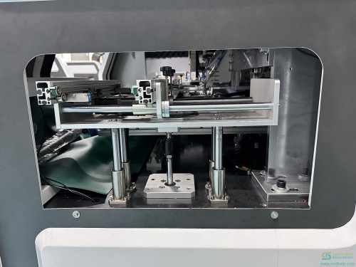
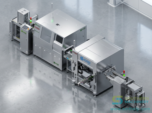
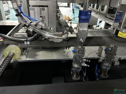
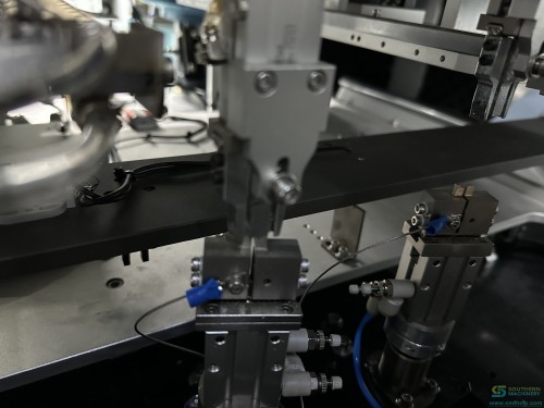
S7000 / S7020T odd-form terminal insertion machine, front viewInsertion area of the S7020T terminal insertion machineInsertion and clinching head of the S7020TPanasonic servo drive cabinet inside the S7020TPCB transport channel of the S7020T terminal inserterS7020T odd-form insertion machine with loader on a THT line
0.6 s/point
Theoretical insertion speed for tact switches — 0.55 s/point for connectors and copper inserts
380 × 280 mm
Maximum PCB the machine accepts; minimum 80 × 80 mm
0.015 mm
Automatic vision correction accuracy — the machine re-finds the holes, not the operator
1–4 heads
Insertion heads, optional — the same frame scales from one terminal type to four
Specifications from the S7020T Use's ManualCapability data from the S-7000T solution sheetEvery disagreement between the sources is published, not hidden
01 — Why it matters

Hand-inserted terminals are a quality problem wearing a labour-cost disguise

Tact switches, strip connectors and copper inserts are the parts a placement machine cannot handle: too tall, too irregular, too much force required. So they go in by hand — and hand insertion is where bent legs, unseated terminals and inconsistent clinch height come from. The cost shows up twice: once in the operators you pay, and again in the rework and field failures you did not plan for.

01

The insertion force is not a judgement call

A terminal needs a defined force to seat correctly, and the board underneath needs that force to stay under its own limit. A hand press gives you neither number. The S7020T detects insertion force on every cycle and stops before the pressure damages the terminal or the PCB.

02

Bent legs come from alignment, not from care

The manual lists "bad bent feet" as a named fault with three causes — insertion inaccuracy, upper and lower heads out of centre, and the wrong gap between head and PCB. All three are mechanical settings. An operator cannot hold 0.05 mm repeat positioning by eye; the machine holds it by design.

03

Manual insertion scales with your order book

Every extra thousand boards a month means another pair of hands at another bench, plus training, plus variation between shifts. Machine insertion converts that into a program and a feed path: the second thousand boards cost you machine time, not headcount.

02 — The process

Six steps from a loaded PCB to a clinched terminal

This is the sequence the manual describes for a production run. The vision correction happens per board, not once per program — which is why the same program holds across board batches that were etched slightly differently.

01

Load and clamp

The board enters on the track. The workbench adjusts its own width to the size entered in the program, the board locates against fixed corners and clamps. The manual states 3 seconds for PCB installation time.

02

Vision correction

A camera reads the actual hole positions and compares them with the NC data. The machine corrects the deviation itself — automatic correction accuracy 0.015 mm — instead of trusting the nominal coordinates.

03

Feed the terminal

Tape feeder for axial braided terminals, bowl feeder plus track for bulk tact switches, strip connectors and copper inserts. Feeding is servo-controlled so each terminal arrives at a repeatable position.

04

Insert under force control

The head drives the terminal into the hole while insertion force is monitored. Excess pressure stops the cycle rather than deforming the terminal or the board — the manual lists this as a standard function.

05

Clinch and verify

Inward clinching, outward clinching or an N form, depending on the joint the product needs. The clinching system detects that each insertion completed successfully before the machine moves to the next point.

06

Log and unload

Output, insertion rate and working time are recorded automatically. The board leaves on the track — manual load or automatic PCB load/unload, depending on how the line is configured.

03 — The machine

Vision, servo motion and a head that reports what it just did

Three subsystems decide whether an insertion is good: where the head thinks the hole is, how repeatably the axes move, and whether the machine notices a bad cycle. The S7020T answers all three — and the photos below are of this machine family, not stock images.

01

The camera corrects, it does not just look

Vision is used for three separate jobs in the manual: correcting the hole-position deviation against NC data, letting the operator program a new board visually, and checking the insertion result. The programming claim is specific — a new PCB insertion program within 5 minutes, using the camera rather than coordinate entry.

02

Panasonic servo motion throughout

Panasonic controller and motors drive the axes, with a worktable resolution of 0.001 mm/pulse. Point-to-point positioning is stated at 0.025 mm and repeat positioning at 0.05 mm. The servo cabinet photo on this page is from this machine family.

03

Mistake-proofing built into the workflow

Before production the operator scans the material QR or barcode, so the wrong reel cannot be loaded unnoticed. Empty-position patching can be set for 0–2 attempts. Insertion force is monitored. Three separate checks that a manual bench simply does not have.

Verified dataCamera programming time, servo make, resolution and force detection are stated in the S7020T manual and the S-7000T solution sheet.
04 — Specifications

The published numbers, and where the documents disagree

Two tables follow. The first is the S7020T specification table, quoted from the machine's own manual. The second lists the points where the manual, the S-7000T solution sheet and the S-7000 presentation give different answers — published here rather than resolved quietly, because you will be buying against these numbers.

S7020T specification table

Verified dataSource: S7020T Terminal Insertion Machine Use's Manual, section 2.2
ParameterPublished value
Insert part objectTact switch · strip connector · copper insert (iron) · axial braided
Packaging acceptedBulk for tact switch, connector and copper insert · 52 mm tape for axial braided
Theoretical speed0.6 s/point tact switch · 0.55 s/point connector · 0.55 s/point copper insert · 1 s/point axial braided
PCB sizeMinimum 80 × 80 mm · maximum 380 × 280 mm
Feeding systemBowl feeder + track (switch, connector, copper insert) · tape feeder (axial braided)
Control systemIntelligent insertion control system on a Windows platform
Display system17 inch colour LCD
X-Y worktable mobile unit0.001 mm/pulse
Positioning accuracyPoint to point 0.025 mm · repeat positioning accuracy 0.05 mm
Automatic correction accuracy0.015 mm
PCB installation time3 seconds
Programming functionsOnline visual programming, visual correction, Excel format
Special functionsAutomatic width adjustment · material QR code scanning · insertion force detection (optional)
Data inputUSB · manual entry
Communication interfaceRS-232C
Noise70 dB
Power supplyAC220V ±10V single phase · 50/60 Hz · 1.6 kVA · 2.0 kW maximum
Air supply5–6 kgf/cm² · compressed air consumption 0.6 m³/min
Dimension2160 × 1330 × 1530 mm
Weight1500 kg

Terminal and clinch capability

Verified dataSource: S-7000T terminal insertion solution sheet — the S-7000T family document
ParameterPublished value
Terminal thickness≥ 0.5 mm and ≤ 1.2 mm
Vertical error≤ 0.8°
Insertion angle360°, in 1° increments
PCB hole requirementInsertion hole 0.5 ± 0.1 mm larger than the component foot
Body distanceDistance between components ≥ 2 mm
Clinch modesInward clinching · outward clinching · N form
Insertion rateUp to 2 insertions per second at 5.08 mm pitch
Stress standardIPC-9704 stress test, within ±400 µε per insertion
Insertion heads1 to 4, optional

Where the documents disagree

To be confirmedThe three source documents give different answers for the following. Confirm against the final quotation drawing before ordering.
ItemS7020T manualS-7000T sheetS-7000 presentationWhat to do
Overall dimension2160 × 1330 × 1530 mm1700 × 1300 × 1600 mm (2 heads)Not statedFootprint depends on head count — confirm the drawing for the configuration quoted
Machine weight1500 kg1200 kgNot statedFloor loading and lifting plan must use the confirmed figure
Throughput0.6 s/point → about 6000 points/hour (tact switch)6000 CPH8000 CPH spec speedState the terminal type and head count with any throughput figure — the three are not measuring the same thing
Power1.6 kVA (2.0 kW max)2 kVA2.0 kVASize the supply for the higher figure until the electrical drawing confirms it
Operating humidity20–95% RH30–70% RHNot statedThe narrower range is the safer planning assumption for a conditioned shop floor
Air pressure5–6 kgf/cm² in the spec table; 0.4–0.6 MPa at start-up; 0.5–0.6 MPa in daily maintenanceNot statedNot statedEven inside one manual the figure is written three ways. Supply 0.6 MPa and regulate down at the machine
Model designationS7020TS-7000T (document title)S-7000The supplied sheet is titled S-7000T while the machine manual is S7020T. Confirm the exact model code on the quotation
05 — Configuration

What you choose before the machine is built

Almost every S7020T is specified rather than picked off a shelf. These are the decisions that change the price, the footprint and what the machine can feed — worth settling before you compare quotations.

Head count

One to four insertion heads. More heads means more terminal types in one pass, and a larger machine — the 1700 mm and 2160 mm length figures belong to different configurations.

Feeding method

Bowl feeder with track for bulk tact switches, connectors and copper inserts; tape feeder for axial braided terminals on 52 mm tape. The choice follows your packaging, not the other way round.

Clinch form

Inward, outward or N. This is a mechanical tooling decision tied to the joint strength your product needs — settle it with a sample board, not from a catalogue.

Load and unload

Manual board load, or automatic PCB load and unload for an in-line configuration. Automatic handling changes the line layout and the conveyor interfaces.

To be confirmedOptional items are listed as optional in the source documents. Which options are fitted to a specific machine is confirmed on the quotation, not on this page.
06 — Installation

What the machine needs from your floor

The manual is specific about the start-up checks and the services. Get these right and commissioning is a day; get them wrong and the machine sits waiting for an electrician.

Before you switch on

Check the power supply. Check the air pressure gauge on the left of the machine. Check the working area for foreign objects that could cause a fault or an injury. The manual lists these three as the pre-start checks.

Power

AC220V ±10V single phase, 50/60 Hz. The manual states 1.6 kVA with a 2.0 kW maximum; the solution sheet states 2 kVA. Size the circuit for the larger figure.

Air

5–6 kgf/cm² at the machine, with consumption around 0.6 m³/min. Regulate at the machine rather than relying on line pressure.

Environment

The manual gives 5–25 °C and 20–95% RH, out of direct sunlight and away from condensation, splashing water, oil and chemical liquids. The solution sheet gives 30–70% RH — plan for the tighter range.

The industrial PC is dedicated

The manual states plainly that the computer on the machine is for this machine only. No other software, and no untrusted USB media — that is how control systems get corrupted.

Shut down in order

Exit the application, exit Windows, then cut the power. Restarting by pulling the supply risks the data and the hard disk. After a power failure, wait 10–20 seconds before restarting so the internal circuits initialise.

07 — Payback

Put your own numbers in and see the payback period

Every money figure below is yours. The only machine value used is the published insertion speed — 0.6 seconds per point for tact switches — because that is the one number we can cite from the manual. Change it to match your terminal mix if your parts are slower.

Manual insertion hours per month—
Machine hours for the same output—
Operator hours released per month—
Labour cost released per year—
Payback period—

Labour saving only. Yield improvement, rework reduction and floor space are not counted — they make the real payback shorter, not longer.

09 — Videos

See the machine insert, clinch and run

Six clips from our own channel — dual-head terminal insertion, the 4-head configuration on power boards, the start-up sequence from the operator manual, and mixed-component demos. Click to play.

10 — Insights

Eight reads on inserting terminals that stay inserted

What we have learned putting terminal insertion machines onto EMS floors — written the way we explain it to customers: the problem first, a method you can reuse, and the honest numbers. Full articles in English; the summaries follow in your language.

ARTICLE 01A bent terminal leg is not a careless operator

Bent legs get blamed on the operator. The manual lists three causes and all three are machine settings. Here is how to find out which one you actually have.

Articles are marketing commentary. Machine facts quoted inside them come from the S7020T Use's Manual and the S-7000T solution sheet.

Walk onto any THT floor and you will hear the same sentence: "she bends the legs." It is said with affection and it is almost always wrong. Look at the machine manual's fault table and bent feet appear as a named fault with three distinct causes — inaccurate insertion, the upper and lower heads out of their correct central position, and the wrong gap between the insertion head and the board. Not one of them is a carelessness problem.

This matters commercially, because the three causes have three different prices. Insertion inaccuracy is a coordinate problem: the vision system corrects it, and the fix is a re-correction and a re-check of the program. Head centring is a mechanical alignment job against the clamping head. The head-to-board gap is a height adjustment on the insertion head and the bottom mould. If you treat all three as "the operator needs to be more careful", you will spend months on retraining and fix nothing.

So the first move is diagnostic, not corrective. Take the ten most recent bent-foot boards and sort them by position on the board. If the failures cluster in one region, you have a coordinate or clamping problem. If they follow one head, you have a centring problem. If they scatter uniformly, look at the gap setting — it is the one that affects every insertion equally.

Then measure the thing you cannot see. The solution sheet states vertical error at 0.8 degrees or less and the PCB hole requirement as 0.5 ± 0.1 mm larger than the component foot. Those two numbers define the window you are working inside. A leg that is 0.9 degrees off is not "a bit bent" — it is outside specification, and it will fail a pull test long before it fails visually.

The loop that keeps this from coming back is a monthly check, not a daily one: head centring, clinch mould alignment, and the head-to-board gap are all on the manual's monthly maintenance list. Put them on a card, sign it, and the bent-foot conversation stops being about people.

ARTICLE 02The hole is 0.5 mm too big, and that is the design

Insertion holes are deliberately oversized. Understanding why turns a recurring argument between design and production into a single number on a drawing.

Articles are marketing commentary. Machine facts quoted inside them come from the S7020T Use's Manual and the S-7000T solution sheet.

Design engineers and insertion engineers argue about hole size more than about anything else, and the argument is almost always a misunderstanding. The solution sheet gives the requirement plainly: the insertion hole should be 0.5 ± 0.1 mm larger than the component foot. That is not sloppy tolerance. It is the clearance the insertion process needs to work at all.

Think about what has to happen in the few hundred milliseconds of an insertion. The terminal has to enter a plated hole without shaving the plating, without pushing the lead sideways, and without requiring a force that deforms either the terminal or the board. A hole exactly the size of the foot leaves no room for the accumulated error of board drilling, plating thickness, terminal stamping tolerance and machine positioning. The clearance absorbs all of it.

What goes wrong when the hole is too small is not subtle. The insertion force climbs, and the force detection stops the cycle — which is the machine doing its job, but it costs you throughput and it looks like a machine fault when it is a board fault. If the force detection is not enabled, the terminal goes in anyway and the plating is damaged. That board passes visual inspection and fails in the field.

What goes wrong when the hole is too large is slower and more expensive. The terminal has room to sit off-centre, the clinch forms asymmetrically, and the joint holds less than it should. You will not see it on the line. You will see it on a vibration test, or in a customer's return.

The method to reuse is this: put the hole diameter on the fabrication drawing as a derived dimension, not an independent one. State the terminal foot dimension, then state the clearance. When the terminal changes, the hole follows automatically instead of staying at a number someone chose three years ago.

And check it the way the manual checks everything else — with the camera. The vision system already reads the hole positions to correct insertion. A periodic check of the measured hole size against the drawing costs nothing and catches the drift before it becomes a batch.

ARTICLE 03Why we publish the numbers our documents disagree on

Our own spec sheet and manual give different dimensions, weights and power figures for the same machine family. We put them side by side on the page instead of picking one.

Articles are marketing commentary. Machine facts quoted inside them come from the S7020T Use's Manual and the S-7000T solution sheet.

Read the specification table on this page and then read the disclosure table under it, and you will find that we publish our own inconsistencies. The machine manual says 2160 × 1330 × 1530 mm and 1500 kg. The solution sheet says 1700 × 1300 × 1600 mm and 1200 kg. The manual says 1.6 kVA, the solution sheet says 2 kVA, the presentation says 2.0 kVA. We could have quietly chosen the nicest set. We did not.

The reason is arithmetic. You are going to size a floor, a breaker and a lifting plan against these numbers. If we give you one figure and it turns out to be the other one, your electrician has already run the cable. The cost of our inconsistency lands on your site, and that is not a cost we are willing to transfer.

There is also a second, more useful reason. Once you know the dimension varies with head count — one to four heads is an option on this machine — the disagreement stops looking like an error and starts looking like information. A 1700 mm machine and a 2160 mm machine are probably the same family at different configurations. We do not know that for certain, which is exactly why the row says "to be confirmed" rather than offering a confident guess.

What we can tell you is the process: before you order, ask for the outline drawing for the exact configuration on your quotation. Not the family drawing, not the brochure dimension — the drawing with your head count and your feeding arrangement on it. That document resolves every row in the table above.

The reusable habit here is broader than machine buying. When a supplier gives you a single number without a source, you have no way to know whether it is a measurement, an estimate or a translation of an old brochure. When a supplier gives you three numbers and tells you why they differ, you can see the shape of their uncertainty — and you can plan around it.

We would rather be the second kind of supplier and lose the occasional order to someone with a cleaner-looking datasheet.

ARTICLE 04Six thousand points an hour is a claim, not a plan

Theoretical speed and real output are different numbers. Here is how to get from one to the other before you sign a quotation.

Articles are marketing commentary. Machine facts quoted inside them come from the S7020T Use's Manual and the S-7000T solution sheet.

The manual gives 0.6 seconds per point for tact switches, 0.55 for connectors and copper inserts, and 1 second for axial braided parts. The solution sheet gives 6000 CPH. The presentation gives 8000 CPH. Multiply 0.6 seconds out and you get about 6000 points an hour — so at least two of those three agree, provided you notice that the 8000 figure is describing a different configuration.

Now subtract everything that is not insertion. Board load and clamp takes three seconds, and it happens once per board rather than once per point — which is why points per board changes your real throughput more than speed does. Twenty-four points on a board is a very different economic proposition from four points, even at identical insertion speed.

Then subtract the stoppages the manual tells you to expect. Poor insertion stops the cycle and raises an alarm; the operator confirms the position and presses the space bar twice to continue. Empty-position patching runs up to two attempts. Feed problems — the fault table lists four separate causes for blocking and irregular feeding — take the machine down until someone clears the track.

A realistic planning figure is usually between sixty and eighty per cent of the theoretical number, and the way to find your own figure is to run a sample batch rather than to argue about the datasheet. Send us your board and your terminals and we will time an actual run.

The reusable method: model throughput per board, not per point. Take the insertion speed, multiply by the points on your board, add the load and clamp time, add a stoppage allowance you have measured rather than guessed, and you have a number you can put in a capacity plan. Anything less is a datasheet.

And if a supplier quotes you a single CPH figure without asking about your terminal mix, ask them which terminal they measured.

ARTICLE 05Force detection is the cheapest insurance on the machine

A terminal pressed too hard damages the terminal and the board at the same time. One function catches both, and it is listed as optional.

Articles are marketing commentary. Machine facts quoted inside them come from the S7020T Use's Manual and the S-7000T solution sheet.

The S7020T manual describes insertion force detection in one sentence: it automatically detects the insertion force during production to prevent excessive pressure from damaging the material and the PCB board. One sentence, two failure modes prevented, and it appears on the specification table marked optional.

Consider what it is protecting. A terminal is a stamped part with a defined cross-section and a plating. Press it past its yield point and the plating crazes, the body distorts, and the retention force drops — but it still looks inserted. A PCB is a laminate with copper on both faces. Press past its limit and you get a witness mark on the surface, a cracked pad barrel, or delamination that only shows up after thermal cycling. Neither failure announces itself at the machine.

Without force detection, the machine has no idea whether a cycle went well. The clinching system detects that insertion completed, which is a position check, not a force check. A terminal that needed twice the normal force to seat still completes, still clinches, and still passes. You find out in the field.

With detection enabled, an over-force cycle stops the machine. That is inconvenient — it costs throughput and it needs an operator decision. But it converts a silent field failure into a loud line stoppage, and line stoppages are cheap compared with warranty returns.

The loop here is a maintenance habit rather than a feature: the yearly maintenance list includes checking whether all equipment status signals are normal and whether the sensors are good. Force detection is one of those sensors. A sensor that has drifted reads every cycle as acceptable, and you are back to having no protection at all while believing you have it.

If you are specifying a machine, specify force detection as standard. The premium is small and the alternative is discovering your plating damage rate from your customer.

ARTICLE 06Vision is three functions, and most buyers only price one

A camera on an insertion machine does correction, programming and inspection. Buyers usually evaluate the first and forget the other two.

Articles are marketing commentary. Machine facts quoted inside them come from the S7020T Use's Manual and the S-7000T solution sheet.

Ask a buyer what the vision system on a terminal inserter is for and you will get one answer: it finds the holes. That is correct and it is the smallest of the three jobs the manual gives it.

The first job is correction. The camera detects the deviation between the actual PCB hole positions and the NC data, and the machine corrects for it. The stated automatic correction accuracy is 0.015 mm. This is what makes the same program work across board batches that were etched or drilled slightly differently, and it is why you do not need to re-teach a program when the fabrication supplier changes.

The second job is programming. The solution sheet states that an operator can finish a new PCB insertion program within five minutes using the camera, and the manual lists online visual programming and visual correction as the programming functions. Think about what that replaces: an engineer at a CAD station, extracting coordinates, exporting a file, walking to the machine, running a test board, and iterating. Five minutes at the machine versus an afternoon of coordination is a different kind of saving from the labour the machine replaces — it is engineering time you get back.

The third job is inspection. The solution sheet notes that vision component inspection finds quality problems before insertion, which is what makes the machine usable in pin-in-paste processes where you cannot afford a bad insertion. It also appears in the yearly maintenance list as something to check: camera recognition function, and the deviation ratio of the part hole size.

Most quotations price the camera as one line item, and most buyers evaluate it as one capability. The reusable move is to test all three on a sample board during evaluation: give the supplier an unfamiliar board and time how long programming takes; run a batch with deliberately varied hole positions and see whether correction holds; and ask what the vision system does when it sees a bent terminal before insertion.

If the answer to the third question is "nothing", you have bought a coordinate reader rather than a vision system.

ARTICLE 07Feeding decides more than the insertion head does

The manual's fault table is dominated by feeding problems. That is a hint about where your uptime actually goes.

Articles are marketing commentary. Machine facts quoted inside them come from the S7020T Use's Manual and the S-7000T solution sheet.

Count the entries in the S7020T fault table and you will notice something. There are eight fault categories, and the feeding-related one — blocking and irregular feeding — carries four separate causes with four separate remedies. No other category has that many. The machine is telling you where it expects to give you trouble.

The four causes are specific: poor track feeding, a misaligned feed track, a material channel that is scratched or carrying oil and debris, and quality problems in the materials themselves. Notice that three of the four are setup and maintenance, and the fourth is incoming quality. None of them is an insertion problem.

This changes what you should evaluate. Buyers spend their time on head count and insertion speed. The manual suggests spending it on feed paths: which feeder handles your packaging, how the track is aligned to the X slider, whether the discharge port of the bowl is aligned with the feed port of the long track, and how easily an operator can clear a jam without tools.

The packaging decision follows from this. Bulk tact switches, strip connectors and copper inserts go through a bowl feeder and track; axial braided terminals on 52 mm tape go through a tape feeder. If your terminal mix spans both, you are specifying a machine with two feed systems, and the feed arrangement — not the head — becomes the thing that determines your changeover time.

The maintenance loop is on the manual's monthly list: clean all tape feeders and tracks. That single line, done on schedule, prevents two of the four causes. The yearly list adds dismantling the feeder for maintenance and redoing standard debugging.

So when you compare quotations, ask each supplier to show you the feed path for your actual terminal, loaded, running, and being cleared after a deliberate jam. That is ten minutes that will tell you more than a page of CPH figures.

ARTICLE 08What to ask before you sign the terminal insertion quotation

Nine questions, in the order that matters, each one answerable from a document rather than a promise.

Articles are marketing commentary. Machine facts quoted inside them come from the S7020T Use's Manual and the S-7000T solution sheet.

Buying a configured machine is not like buying a catalogue item, and the difference shows up in the questions. Here is the list we would use if we were the buyer, in the order that saves the most money.

One: which model code, exactly? The documents we hold title the same family as S-7000T and S-7000 and S7020T. Ask for the code on the quotation and the drawing that goes with it. This single question resolves most of the ambiguity that follows.

Two: how many heads, and therefore what footprint? Head count is an option from one to four, and the dimension figures in our own documents differ by configuration. The answer determines your floor plan.

Three: what does the machine weigh? 1200 kg or 1500 kg in our own documents. This determines your lifting plan and possibly your mezzanine.

Four: what are the real electrical requirements? 1.6 kVA, 2 kVA and 2.0 kVA all appear. Ask for the electrical drawing, and size the supply for the largest figure.

Five: which feeder for my packaging? Send a reel and a bag of your actual terminals. A quotation that does not reference your packaging is a quotation for a machine, not for your process.

Six: which clinch form, and who decides? Inward, outward or N. The right answer depends on the joint your product needs, which means it comes from a pull test on a sample, not from a catalogue.

Seven: is force detection included? It appears as optional in the specification table and it is the cheapest protection on the machine. Get it in writing either way.

Eight: what is the spare parts position? The clinching mould, the press cover, the tracks and the belts all appear on the maintenance list as wear items. Ask for the wear-part list with prices before you order, not after the first breakdown.

Nine: what does commissioning include, and what does it assume? The manual's pre-start checks assume power, air at 5-6 kgf/cm², and a clear working area. Confirm who provides what, and get the training scope in writing.

None of these questions requires technical depth. All nine are answerable from documents the supplier already has. The suppliers who answer them quickly are the ones who will answer quickly when the machine is down.

11 — Documents

The source documents behind every number on this page

Machine manual, family solutions and the 3D model. Read them the way we did — and check our disclosure table against them.

S7020T Use's Manual

The machine's own operating manual — safety, specification table, operation steps, parameter setting, maintenance schedule and the fault table.

Open the PDF

S7020 Series — PIN, eyelet and terminal insertion

The S7020 series product document covering PIN, eyelet and terminal insertion configurations.

Open the PDF

S7020 THT odd-form insertion

Product description for the THT odd-form insertion configuration — the parts this machine family is built to handle.

Open the PDF

S-7000 odd-form insertion manual (2024)

The wider S-7000 odd-form platform manual. Useful for understanding what the family shares — not a substitute for the S7020T document.

Open the PDF

S-7000E eyelet insertion solutions

Eyelet insertion variant of the same platform — relevant if your board carries eyelets alongside terminals.

Open the PDF

S7000 feeder 3D model

Radial, axial and tube feeder arrangement as a 3D drawing — useful for layout work in your own CAD.

Open the PDF
12 — Maintenance

The maintenance schedule the manual actually specifies

Daily, monthly and yearly. We have kept the manual's own wording for the checks, because paraphrasing a maintenance instruction is how a machine gets serviced wrongly.

Daily

Air and cleanliness

Check that the air pressure is normal at 0.5–0.6 MPa. At the end of the shift, clean the dust off the machine and wipe away excess grease.

Monthly

Wear, alignment and tension

Wipe and re-grease the polished rods, screw rods and linear slides. Check the press cover and clinching mould for wear and deformation. Check the pneumatic components. Check the floating joints. Check belt tension, length and wear. Clean all tape feeders and tracks. Check drive shafts and bearings. Check each head's centre position and the alignment of the clinching mould to the head. Check the wiring for leakage or ageing.

Yearly

System-level checks

Check all solenoid valves and cylinders and measure their speed and response. Check motor and servo coordination and screw-rod tightness. Check the main air valve, muffler and air circuit. Clean the host computer and check its fan. Check all shell exhaust fans. Check all status signals and sensors. Check camera recognition and the part-hole deviation ratio. Dismantle the feeder for maintenance and redo standard debugging. Use slow-motion video of each head's insertion movement and adjust axes and cylinder pressure if coordination is off.

Fault to first check

Verified dataSource: S7020T manual, section 7.2 — common faults and handling methods
SymptomCause the manual namesFirst thing to check
Poor insertionBad picking of the clamping head · inaccurate insertion coordinates · no parts detectedIs the clamp loose or damaged; then correct coordinates and head offset; then check the detection line and the bottom mould position
PCB leakageBottom formwork short circuit · detection line short circuitInsulating plate and screw insulating sleeve for damage, then measure the detection line voltage at the bottom mould with a multimeter
Blocking, irregular feedingPoor track feeding · misaligned feed track · scratched or contaminated material channel · defective materialAlignment between the bowl discharge port and the long track feed port; then alignment of the long track to the X slider and the short track
Bent feetInaccurate insertion · heads out of centre · wrong head-to-board gapVision correction and PCB fixing first, then head centring, then the insertion head and bottom mould height
Servo alarmForeign matter on the front axle · servo alarmClear foreign matter; clear the alarm on the servo and re-read the servo parameters from the main page, then return to zero
Start button does nothingPower supply · air supply · safety sensor · emergency stop latched · otherPower and circuit continuity, then air valve and pressure, then the safety sensor status in the device status screen
Vision cannot be correctedCamera cable broken or poorly seated · light source or camera parameters wrong · foreign matter in the camera or the calibration holeCamera cable and interface first, then light intensity and camera parameters, then clean the camera and the calibration hole
Board transport timeoutTrack width · tracks not parallel · height mismatch between rails and workbench · track deformed · pressing cylinder speed · conveyor motor speedTrack width and parallelism first, then rail heights, then the pressing plate cylinder throttle
To be confirmedFault handling is for qualified personnel only. Make the machine safe under your site procedure and follow the current manual before intervening. This page is not authorisation to service or to bypass an interlock.
13 — FAQ

Questions this machine always raises

Which terminals can the S7020T actually insert?
The manual's specification table lists four object types: tact switches (bulk), strip connectors (bulk), copper inserts or iron inserts (bulk) and axial braided parts (52 mm tape). The presentation adds tact switches with an outer diameter of 6.0 × 6.0 to 10 × 10 mm and a handle length of 3.5 mm or less as a component example. Send us a sample of your terminal and we will confirm the feed path and tooling for it.
How many insertion heads should I specify?
One to four, and the answer is driven by how many different terminal types you want inserted in a single pass. More heads means fewer passes over the board but a larger machine — our own documents give different dimensions for different configurations. Tell us your board and your terminal mix and we will recommend the head count with the reasoning.
Is 6000 or 8000 pieces per hour the real figure?
Both numbers appear in our own documents, and neither is a lie — they are not measuring the same thing. The manual gives 0.6 s/point for tact switches, which works out at roughly 6000 points per hour, and the solution sheet states 6000 CPH. The presentation's 8000 CPH is a family specification speed for a different configuration. Any throughput figure is meaningless without the terminal type and head count beside it, which is why our disclosure table lists the three side by side.
Do we need force detection?
It appears as optional in the specification table, and our recommendation is to specify it. It stops the machine when insertion force exceeds the limit, which prevents both terminal deformation and PCB damage in the same cycle. Without it, an over-force insertion completes and clinches normally and you only find out from a field failure. It is the cheapest protection available on this machine.
What board do I need to send for an evaluation?
A populated board as close to production condition as possible, plus a representative sample of every terminal type you want inserted — including the packaging it arrives in. The packaging decides the feeder, and the feeder decides the configuration. Five to ten boards is usually enough to time a realistic run and confirm the clinch form.
Can it run in line with our existing THT equipment?
The solution sheet lists manual load or automatic PCB load and unload as configurations, and our photo library shows this machine family running in line with a loader alongside axial and radial inserters. Whether your specific line can take it depends on your conveyor interfaces and board flow direction, which we would need to look at together. RS-232C is the stated communication interface and can connect to an MES system.

Send us a board and a bag of terminals

We will confirm the feeder, the clinch form, the head count and a realistic throughput for your product — and tell you plainly which of our own documents disagree.

14 — Contact

Tell us what you are inserting

Terminal type, packaging, board size and the number of insertion points. That is enough for us to come back with a configuration and a price.

Reach us directly

info@smthelp.com
WhatsApp +86 136 0256 2576
www.smthelp.com

Shenzhen Southern Machinery Sales and Service Co., Ltd. — Xixiang, Bao'an District, Shenzhen, China. Established 2011.

Before you write

Have a look at our disclosure table in section 04 first. If you are comparing our numbers against another supplier's, that table tells you exactly which of ours are firm and which need confirming against your quotation drawing.

✆