
Shenzhen Southern Machinery - SMT / THT equipment design and manufacturing since 2011
Southern Machinery Southern MachinerySMT / THT equipment and board handling
Pre-scored V-cut boards - moveable blade

S-D508 V-Cut PCB Depanelizer
for Smart EMS PCB Assembly

A round blade travels the length of the score line while a flat blade backs the panel from underneath. The board is separated along the V-groove instead of being bent over an edge, so the solder joints next to the cut are never loaded.

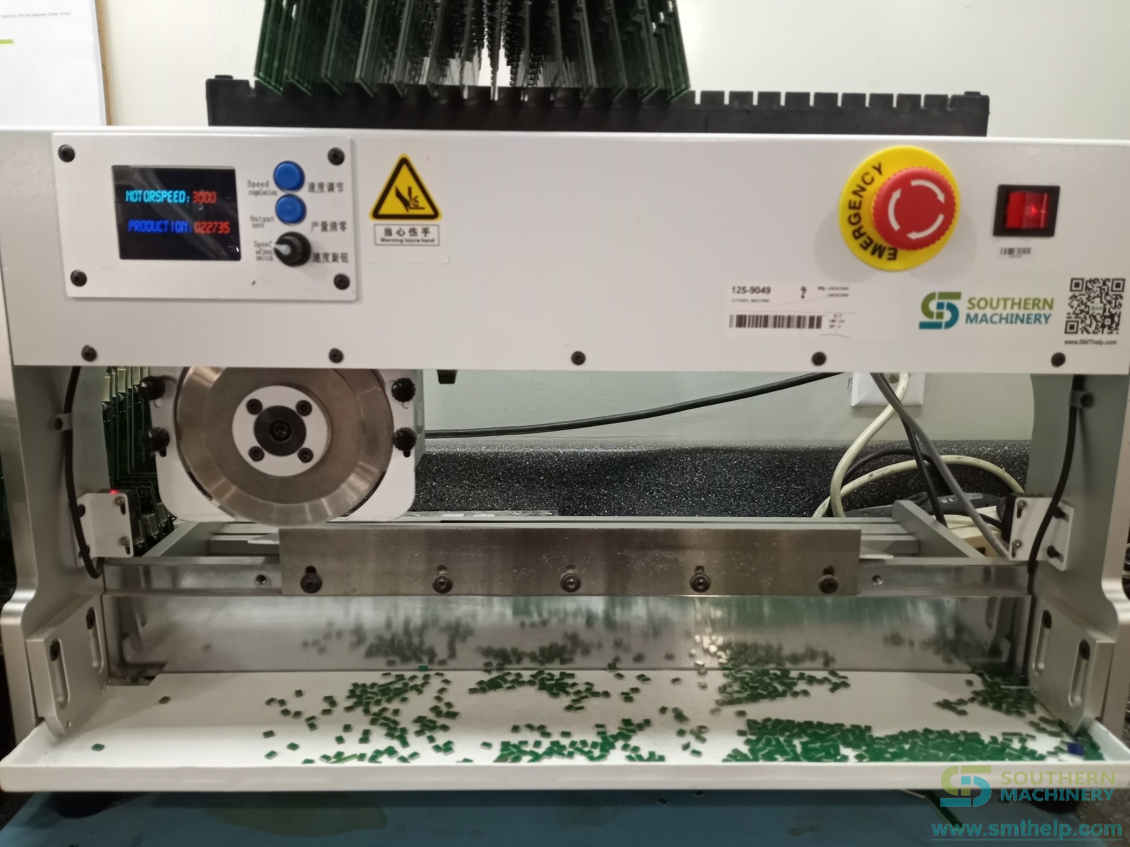
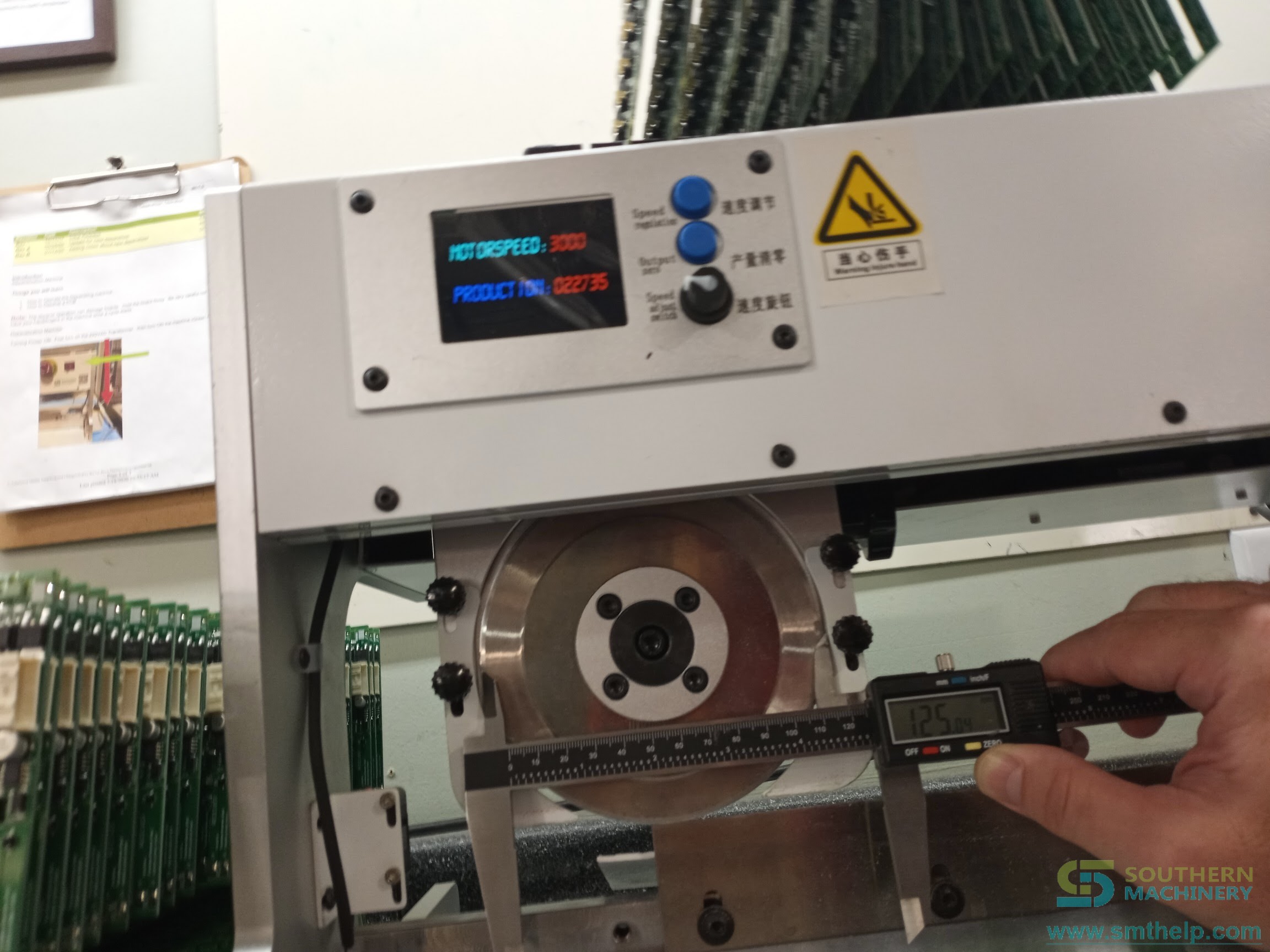
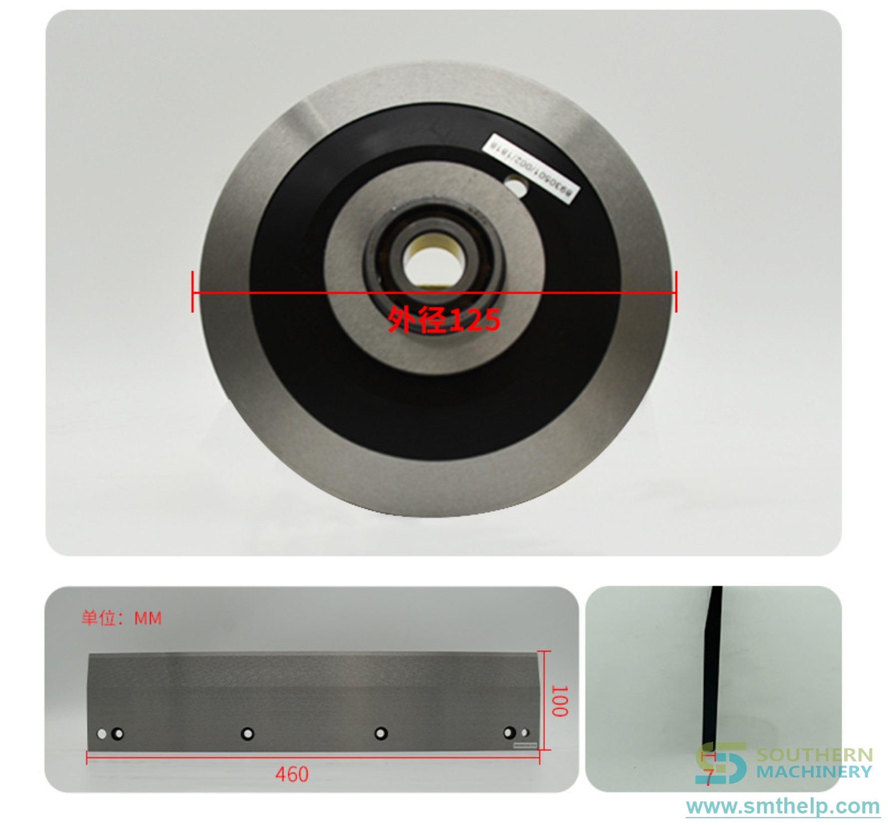
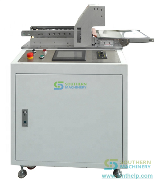
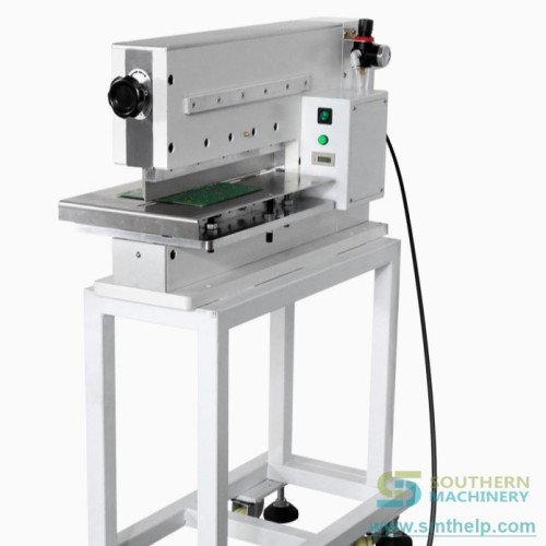
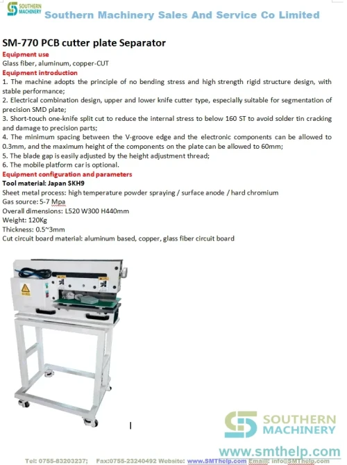
S-D508 V-cut PCB depanelizer, front view with the lower blade across the platformS-D508 cutting head with the round upper blade, speed panel and displayThe Southern Machinery separator series on one page: seven separation machinesMulti-blade separator head travelling above a long aluminium platformUpper round blade and lower straight blade drawing, 125 mm outside diameter and 460 x 100 mm
0.2 - 5.0 mm
Board thickness the platform accepts
300 - 500 mm/s
Blade travel speed, high and low
0.1 - 0.2 mm
Upper-to-lower blade gap setting
0 - 50 mm
Platform height adjustment range
Every specification value names the document it came fromConflicting values are shown side by side, never averagedUnconfirmed values are marked To be confirmed
Why machine separation

Breaking a panel by hand is a yield decision, not a labour decision

A V-score is a controlled weakness, but the panel still has to be separated along it. Snapping it over a table edge works until it does not: the crack finds the weakest point, and the weakest point is often a solder fillet two components away from the score line. Depaneling moves the failure to the place you designed for it.

01

Stress goes into the score line, not the board

A round blade rolling along the V-groove with a flat blade underneath puts the bending moment into the groove itself. The board either side of the cut stays flat, which is what keeps a fillet from cracking and a ceramic capacitor from chipping.

02

A cut edge you do not have to clean up

The brochure describes the result as cut off without fibre and without burr, with the incision forming cleanly. That matters on any board that ships without a wash, and on LED metal-core panels where a raised burr becomes a shorting risk.

03

One machine, any panel length

The blade moves and the panel is supported, so the width of the panel is not a limit. The brochure states no restriction on the width of the target PCB, and the maximum cutting length is set by the blade and the stop position you order.

How it cuts

From a scored panel on the platform to a separated board

The machine is called a moveable V-cut separator for a reason: the panel stays where the operator puts it, and the cutting head travels. The nine stations below follow the operating sequence in the operation manual.

The S-D508 cutting head: the round upper blade under the guard, the blade height knob and the three-button speed panel with its display
S-D508 cutting head close-up: the round upper blade behind its guard, the three-button speed panel and a digital caliper reading 125 mm across the blade
01

Support the panel

The board rests on the platform with the V-groove lined up over the flat lower blade. The platform height is adjustable over 0 to 50 mm.

02

Align the score line

The score line sits directly above the lower blade. The machine is built for boards with a pre-scored V-cut, not for routing or snapping.

03

Set the upper blade height

The upper blade height knob sets how deep the round blade sits in the groove. The brochure gives a fine adjustment of 0 to 2 mm for exactly this.

04

Set the blade gap

The gap between upper and lower blades is set to 0.1 to 0.2 mm, and the two cutters must sit in the same plane to within 0.1 mm.

05

Set the stop point

The travel is set to stop at the panel length. The manual shows the key points as 0, 100, 200, 300 and 400, so the head stops where the panel ends.

06

Press the pedal

The foot switch starts the cycle and the head returns to the origin first, so every cut begins from the same place.

07

The round blade rolls the groove

The upper circular blade travels along the score line rather than descending onto it, which is what keeps the cut straight on a long panel.

08

The flat blade backs the panel

The lower straight blade supports the board right under the cut, so the panel cannot flex away from the blade as the crack opens.

09

Unload, count, repeat

The display carries a motor speed readout and a production total. The field photograph of the unit shows that counter at 622735, so it is a working machine counter rather than a decorative one.

Sequence described from the operating instructions in the S-D508 operation manual and the feature list in the 2019 separator brochure. Blade travel range depends on the cutting length option you order.

LOAD
SELECT
PRESENT
Align the score line - blade travels - panel separates along the groove
Machine fit

Three things decide whether it fits your panel

A depanelizer only works if the panel fits the platform, the score line lands on the blade, and the cut quality is acceptable on your board material. Each of those is a documented feature, not an assumption.

Source: S-D508 operation manual, 2019 separator brochure and the CE certificate
CE

Board material and thickness

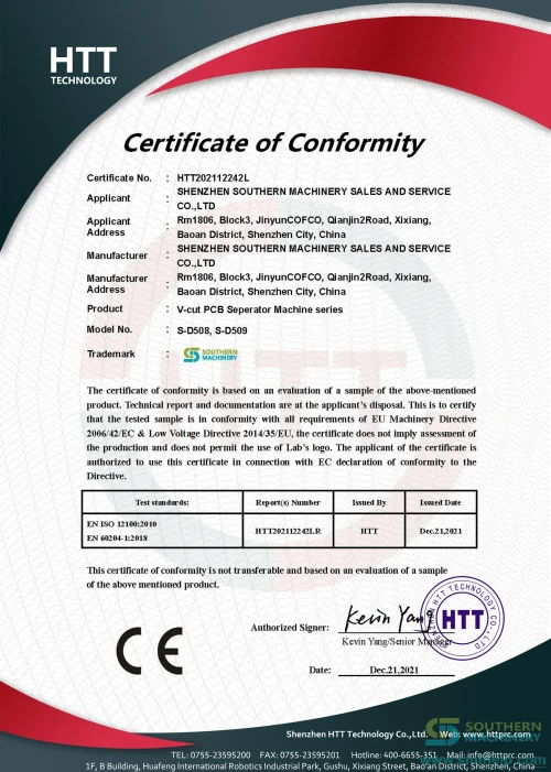
The platform accepts boards from 0.2 to 5.0 mm thick. The separator series is built for V-cut FR4, aluminium-backed and copper boards; the CE certificate names the V-cut PCB Separator Machine series and lists S-D508 and S-D509 by model number.

S-D508

Panel size and score depth

The width of the panel is not restricted, and the maximum thickness across the V-slot is 0.25 to 2.0 mm, which is the number that decides whether your score line can be separated by rolling rather than by force.

S-D508

Component clearance either side of the cut

The operation manual asks you to confirm that no component on the board will collide with the body or the blade, and offers a pre-machined blade if a part sits close to the cut. That is a real constraint, and it is cheaper to check it on a drawing than on the line.

Specification

Specification with sources

Every row names the document the value was read from. Where the sources disagree, both values are shown side by side - read the Open points section before you quote.

Source: six supplied documents, quoted as written
Parameter Separator brochure 2019 - SC-D508 S-D508 operation manual ASC-508 manual (Chinese market) SC-500 / SC-509 sheets
Model codeSC-D508 Moveable V-cut PCB SeparatorS-D508 (named in the speed-regulation section as S-D508/509)ASC-508 走刀式分板机SC-500 and SC-509, two separate sheets
Machine typeMoveable V-cut PCB separator for pre-scored boardsPCB depanelizer, V-cut boards only走刀式分板机 - travelling-blade board separatorV-cut PCB separator with moveable cutting blade
Dimensions (L x W x H)L620 x W400 x H430 mm600 x 395 x 425 mm600 x 395 x 425 mmSC-500 L823 x 405 x 425 mm; SC-509 L1000 x W395 x H425 mm
Weight37 kg37 kg37 kgSC-500 prints 350 kg; SC-509 47 kg
Maximum cutting length360 mm and 500 mm360 mm, or 500 mm as an optionUnlimited (no maximum stated)SC-500 360 mm; SC-509 360 mm
Board thickness accepted0.2 - 5 mm0.2 - 5.0 mm0.2 - 5.0 mm0.2 - 5 mm
Maximum thickness across the V-slot0.25 - 2.0 mmNot statedNot stated0.25 - 2.0 mm
Cutting speed0 - 500 mm/s, adjustable300 - 500 mm per second300 - 500 mm per second300 mm/s and 500 mm/s, high and low
Blade travelNot statedKey points at 0, 100, 200, 300, 400 with a 0 - 400/600 display rangeNot statedSC-500 knife travel 0 - 500 mm; SC-509 knife wheel path 0 - 360 mm
Blade materialImported high speed steel, no grade givenSK61D high speed steel (as printed)SKD61 high speed steelSC-500 prints SHD61; SC-509 prints SKD61 and its FAQ answers Japan high speed steel SKH-9
Upper round blade diameterNot statedNot statedNot stated125 mm on both sheets; a field photograph of the unit shows a caliper reading 125 mm across the blade
Lower straight blade lengthNot statedNot statedNot statedSC-500 500 mm; SC-509 360 mm; the blade drawing in the image library marks 460 x 100 mm
Blade height adjustment0 - 2 mm fine adjustmentBy the upper-blade height knobBy the upper-blade height knob0 - 2 mm
Platform height adjustment0 - 50 mmThe working platform can be adjusted up or downThe working platform can be adjusted up or down0 - 50 mm
Upper-to-lower blade gapNot stated0.1 - 0.2 mm0.1 - 0.2 mmNot stated
Blade coplanarity toleranceNot statedUpper and lower cutters in the same plane, error within 0.1 mmUpper and lower cutters in the same plane, error within 0.1 mmNot stated
Panel width limitNo restriction on the width of the target PCBNot statedNot statedSC-500 maximum cutting width unlimited
Rear stop depthNot statedNot statedNot statedSC-500 and SC-509 rear baffle depth range unlimited
Stop position settingSet manually to the length of the PCBSet by the 0 / 100 / 200 / 300 / 400 key pointsSet by the 0 / 100 / 200 / 300 / 400 key pointsManual stop fixed point
Control systemMicrocomputer control with precision fixed pointKey panel with display, plate trip button, high/low speed switchKey panel with display, plate trip button, high/low speed switchMicrocomputer control with precision fixed point
Display readoutsNot statedMotor speed and a production totalMotor speed and a production totalNot stated
Conveyor / outfeedConveyor belt optional, to transfer the finished PCB outNot statedNot statedSC-509 conveyor belt L1030 x W220 x H130 mm
Working voltage230 V / 50 Hz, or 110 V / 60 Hz230 V / 110 V, 50 / 60 Hz230 V / 110 V, 50 / 60 HzSingle-phase AC 230 / 110 V, 50 - 60 Hz
Power consumption40 W40 W40 W40 W
Operating / storage temperatureNot statedOperating 10 - 35 C, storage -20 to 50 COperating 10 - 35 C, storage -20 to 50 CNot stated
WarrantyNot stated1 year from the date of purchase, lifetime maintenance1 year from the date of purchase, lifetime maintenanceSC-509 FAQ answers 1 year

Parameter by parameter, with the document it came from

All 26 rows are reproduced from the supplied documents. Where a document does not state a parameter, the row says Not stated rather than borrowing a value from another model. Rows where the sources disagree are repeated in Open points.

Open points

Where the documents disagree, both values stay on the page

A specification table that quietly picks one of two numbers is worth less than one that shows both. Six parameters below do not agree across the supplied documents, or are stated in only one of them. Confirm each against the current drawing for your configuration before you place an order.

Status: To be confirmed - not averaged, not silently resolved
Parameter What the documents say What the other source says What the difference means Status
Model namingThe 2019 separator brochure lists the machine as SC-D508 Moveable V-cut PCB Separator.The operation manual and the CE certificate both name it S-D508. The CE certificate covers the series and lists S-D508 and S-D509. The Chinese-market manual calls the same machine ASC-508.Four codes appear across the documents for what is presented as one machine. S-D508 is the code the operation manual and the CE certificate agree on, so it is the one used on this page.To be confirmed
Machine dimensionsBrochure: L620 x W400 x H430 mm. Manual: 600 x 395 x 425 mm. ASC-508: 600 x 395 x 425 mm.The sister models are larger again: SC-500 at L823 x 405 x 425 mm and SC-509 at L1000 x W395 x H425 mm.A 20 mm difference in length and 5 mm in width is within the range of a guard or a tray revision. It is not a rounding error, so both figures stay visible.To be confirmed
Net weightBrochure, operation manual and ASC-508 manual all state 37 kg.The SC-500 sheet prints a net weight of 350 kg.37 kg is consistent across three documents; 350 kg on a machine of this size is almost certainly a misplaced decimal point. Treated as a typographical slip, not as a fact about the machine.To be confirmed
Blade material gradeManual: SK61D. ASC-508 manual: SKD61. Brochure: imported high speed steel, no grade.SC-500 sheet: SHD61. SC-509 sheet: SKD61, and its FAQ answers the blade material as Japan high speed steel SKH-9.Five spellings of what is likely two real grades. SKD61 and SKH-9 are both Japanese tool steels; SK61D and SHD61 are not standard designations. Ask for the grade in writing before you order spares.To be confirmed
Speed controller rangeThe operation manual describes the speed knob as adjusting the motor speed and states the maximum value is in the range of 70.A Southern Machinery field photograph of the unit shows its own display reading MOTOR SPEED 3000 with a production total of 622735.70 and 3000 cannot both be the same scale. Either the manual describes an earlier controller or the display counts in different units. Read the value off your own machine before you write a cycle time into a quotation.To be confirmed
Cutting length and blade lengthBrochure: cutting length 0 to 360 mm, maximum cutting length 360 mm and 500 mm, blade length can be customized.Manual: maximum plate length 360 mm, or 500 mm as an option. The image library blade drawing marks the lower blade at 460 x 100 mm.A 460 mm lower blade in a machine with a 360 mm standard cutting length is consistent with a longer blade under a shorter stop setting, but the documents do not say so. Confirm the blade length you will receive.To be confirmed

This page is not a quotation. Values are reproduced from the documents named in each row; the current drawing for your configuration governs. One further detail is worth knowing: the CE certificate prints the directive as EMC Directive 2006/42/EC, while 2006/42/EC is the Machinery Directive. The certificate number, the issuing body and the covered models are quoted here as they appear on the document.

Throughput

What a single blade is worth per hour

The cut is limited by travel speed, and the cycle is limited by how long it takes to load and unload a panel. The table converts the published 500 mm/s travel speed into boards per hour for three cut lengths, with a stated handling allowance.

Derived from the published 500 mm/s cutting speed plus a 3 s handling allowance
Cut lengthTheoretical boards/hourAt 90 percent availabilityAt 80 percent availability
200 mm1059953847
360 mm968871774
500 mm900810720

Derived arithmetic, not a measured production figure. It counts separated boards, not shipped assemblies, and it assumes one operator loading and unloading the machine. Change the handling allowance and the numbers move with it.

Configuration

What you choose when you order

Each of these is a documented option on the separator series rather than a custom engineering project.

Source: 2019 separator brochure, S-D508 operation manual and the SC-509 sheet

Cutting length 360 mm or 500 mm

The standard machine separates up to 360 mm. The brochure lists 500 mm as the alternative, and states the blade length can be customized.

Conveyor outfeed

An optional belt carries the separated board away from the blade. The SC-509 sheet gives the conveyor as L1030 x W220 x H130 mm.

Stop block for different panels

The brochure describes a stop block that suits different PCBs and raises working efficiency - a mechanical datum rather than a re-programmed stop.

Height-adjustable platform

0 to 50 mm of platform travel, so boards of different thickness and different component heights can be presented at the same working plane.

Blade height fine adjustment

0 to 2 mm on the upper blade, which is the adjustment that solves a V-slot of non-standard depth without changing the tooling.

Spare and re-sharpenable blades

The brochure states the blades can be sharpened again when needed. The SC-509 sheet answers that they can be re-sharpened two to three times.

Commissioning

Six steps from crate to first separated board

The operation manual describes the setup as a sequence: place, earth, connect, power, adjust, then trial. These are the six stations in that order.

STEP 1

Place and earth the machine

Stand it on a flat, solid bench and earth it properly. The manual gives the reason directly: static on the board damages the components before you have even cut it.

STEP 2

Fit the outer tray

Two fixing screws hold the outer tray. Set its height to clear the tallest component on the board, then lock the tray knob screw by hand.

STEP 3

Connect the foot switch

The pedal plugs into the socket on the back of the machine. Confirm the supply voltage before you switch on - the machine accepts 230 V or 110 V depending on build.

STEP 4

Power on and confirm the display

The display shows the motor speed and the production total. The manual notes the indicator lights flash on start-up and that pressing the matching key latches them on.

STEP 5

Set the blade gap and the plane

Upper-to-lower gap 0.1 to 0.2 mm, and the two cutters in the same plane to within 0.1 mm. This is the adjustment that decides cut quality, so do it before anything else.

STEP 6

Trial cut, then run

Step on the pedal and let the head return to the origin, then run a few boards. The manual puts it plainly: if there is no abnormality, formal work can be started.

0.2 - 5.0 mm board 360 / 500 mm cut 230 / 110 V, 40 W 0.1 - 0.2 mm gap 300 - 500 mm/s 37 kg

Setup is a qualified task. The manual asks for the machine to be earthed before use and for the blade guard to stay in place at all times; neither instruction is optional.

Payback

Work out the payback from your own numbers

Nothing on this page asserts a saving. The machine cycle time and the manual breaking-off time are the two numbers that decide the answer, and both are yours to measure. If machine separation is not faster on your panel, the page says so instead of printing a negative.

Depaneling payback

Enter your own cycle time and labour rate

Machine time per board
— s
Handling hours released
— h / month
Labour released
— USD / year
Payback
—
Illustrative model, not a quotation. The machine cycle defaults to 3.7 s, which is a 360 mm cut at the published 500 mm/s plus a 3 s handling allowance. The model ignores rework saved by not cracking joints, blade wear and machine utilisation, all of which affect the real answer.
Working video

The machine separating boards

Selected from the Southern Machinery YouTube board. Titles and running times are the board's own, not re-worded here.

Insights

Eight notes on separating a scored panel

Long-form notes on V-cut depaneling, written for process engineers and production managers who have to make the decision, not just read about it.

ARTICLE 01Snapping a Scored Panel Is a Yield Decision, Not a Labour Decision

The crack goes to the weakest point, and the weakest point is rarely where you planned it.

Full articles are in English. The summary above carries the argument in your language.

A production manager adds up the labour cost of snapping panels by hand and concludes it is small. Two people, part of a shift, a job that takes seconds per board. The arithmetic is correct and it answers the wrong question, because the cost of hand separation is not in the minutes - it is in the boards that fail three weeks later and the ones that fail before anybody measures them.

Breaking a score line by hand applies a bending moment across the whole panel, not just across the groove. The panel flexes, the flex travels to wherever the board is stiffest, and that is usually where a row of solder fillets sits. Some joints crack outright. Others crack partially and pass test anyway, because a hairline crack in a fillet is electrically continuous until thermal cycling opens it. The failure leaves the factory looking like a good board.

The way to see it is to stop measuring labour and start measuring separation quality. Take twenty panels, separate ten by hand and ten on a machine, and inspect the fillets within 20 mm of the score line under magnification. Count micro-cracks rather than outright failures. Then run the same twenty boards through a thermal cycle and count again. The difference between the two groups is the real cost of the manual method, and it is a yield number rather than a wage number.

That is what a moveable-blade separator is built to remove. The S-D508 rolls a round blade along the score line while a flat lower blade backs the panel directly beneath the cut, so the bending moment stays inside the V-groove and the board either side of it stays flat. The brochure describes the result as completely reducing the stress compared with breaking by hand, and states the board is cut off without fibre and without burr.

The habit worth building is a separation audit on the boards with the tightest component-to-score clearance. Those are the boards where a hand snap will eventually cost you a field return, and they are usually a minority of the product mix, which means the audit is cheap. Re-run it whenever a panel layout moves a component closer to the score line.

Pick the board with the least space between a fillet and the score line, and inspect twenty hand-separated panels from it under magnification. If you find micro-cracks, you have your business case already written; if you do not, you have learned something worth knowing about your process.

ARTICLE 02What a Cracked Solder Fillet Costs Before Anybody Sees It

The board passes test, ships, and fails in the field six weeks later.

Full articles are in English. The summary above carries the argument in your language.

The most expensive defect in electronics assembly is the one that passes test. A cracked solder fillet that is still electrically continuous will clear in-circuit test, clear functional test, pass final inspection and ship. It fails in the customer's hands, after a few hundred thermal cycles, and it arrives back as a warranty claim with no traceable cause.

Hand separation of a scored panel is a reliable way to manufacture that defect. The panel is supported at two points, a load is applied, and the crack propagates from the score line outward. Where it stops depends on the local stiffness of the board, the mass of the components nearby, and how the operator happened to hold it. On a densely populated board the crack can reach a fillet without ever looking like a broken board.

The countermeasure is not a training programme, because there is nothing to train: the operator cannot see the crack either. The countermeasure is to change the mechanics of the separation step so that the load path never crosses a solder joint. Support the board underneath the score line, apply the separation force at the score line, and let the panel stay flat. Everything else follows from that one principle.

The S-D508 applies it with a round blade above and a flat blade below, both sitting on the score line. The upper blade height is adjustable over 0 to 2 mm and the gap between the blades is set to 0.1 to 0.2 mm, with the two cutters in the same plane to within 0.1 mm. Those three settings are the whole mechanism: get them right and the separation is a controlled crack along the groove.

Then make the setting part of the record. A depaneling machine that gets re-set by feel after every blade change is a machine that will eventually crack a board, and nobody will connect the two events. Write the gap, the plane tolerance and the blade height on a card inside the machine and re-check them after every blade change.

Measure the gap on your separator today and write the number down. If nobody in the building knows what it is, you have found a risk that costs nothing to close.

ARTICLE 03How to Measure the Stress Your Separation Step Puts on a Board

Three measurements you can take on your own line, with no laboratory.

Full articles are in English. The summary above carries the argument in your language.

You do not need a laboratory to find out whether your separation step is overloading the board. You need a strain gauge, a board, and an afternoon. The measurement is the same one the machine builders use, and it will tell you more than any supplier datasheet.

The reason to measure rather than estimate is that the load depends on the geometry of your panel, not on the method alone. The same manual snap that is harmless on a 1.6 mm board with 30 mm of clear space beside the score line can be destructive on a 0.8 mm board with a connector 5 mm from the cut. The variable that decides it is the distance from the score line to the nearest stiff feature.

Three measurements are enough. First, bond a strain gauge within 10 mm of the score line, on the side away from the cut, and record peak strain during a hand snap. Second, do the same during machine separation. Third, repeat the machine measurement with the platform height deliberately set 5 mm too low, so you can see how much the setting matters. The third number is the one that tells you whether your setup discipline is adequate.

The machine-side numbers you are checking against are documented. The S-D508 takes boards from 0.2 to 5.0 mm and up to 2.0 mm thick across the V-slot, with a platform adjustable over 0 to 50 mm and a blade height fine adjustment of 0 to 2 mm. Those ranges exist precisely so that the blade can be brought to the score line on boards of different thickness without changing the tooling.

Keep the strain figure with the panel drawing, not in a test report nobody opens. When the layout changes and a component moves closer to the score line, the drawing is where the next engineer will look, and a peak strain number beside a component position is a much better warning than a note that says be careful.

Put a strain gauge on one panel this month and record the peak during a hand snap. Even one number, taken once, will change how the separation step is specified in your next process review.

ARTICLE 04Six Checks Before You Retire the Manual Snap Table

A short acceptance routine that stops a depaneling conversion from failing on the line.

Full articles are in English. The summary above carries the argument in your language.

Retiring a manual snap table is a small project with a large failure mode: the machine is proven on a clean sample, the changeover is approved, and then production starts running panels from a different board supplier. The score depth is a fraction different, the blade height that worked perfectly now sits too shallow, and one panel in fifty separates with a burr. Nobody suspects the board, because the machine was proven.

The failure pattern is consistent because the variables are. Score depth varies between panel suppliers and between lots. Board thickness varies within its own tolerance. Component heights vary with the parts you happen to have. Any of those moving by a few tenths of a millimetre changes how deeply the round blade needs to sit in the groove, and none of them are visible from the operator position.

The answer is to accept the conversion formally, with six checks. First, the score depth measured on ten panels from three separate lots. Second, the blade gap confirmed at 0.1 to 0.2 mm and the two cutters confirmed in the same plane to within 0.1 mm. Third, a trial run on each lot, not on one sample. Fourth, a burr and fibre inspection of the cut edge on each lot. Fifth, a magnification check of the fillets within 20 mm of the score line. Sixth, a written changeover procedure that names the blade height, the gap and the stop position so the settings can be restored after a blade change.

The documented figures give you the targets. The S-D508 accepts boards from 0.2 to 5.0 mm with a maximum V-slot thickness of 0.25 to 2.0 mm, separates at 300 to 500 mm per second, and offers a 0 to 2 mm blade height adjustment for exactly the score-depth variation the checks are looking for. If a lot needs a blade height outside that 2 mm window, the panel is the problem rather than the setting.

Then keep the log. The burr rate per lot is the single most useful number for spotting a panel supplier whose score depth has drifted, and it costs nothing to collect once the machine is running. A supplier conversation backed by twenty measured panels is a very different conversation from a complaint.

Write the six checks into the changeover procedure for one panel, run it on three lots, and see what the burr rate actually is. If it is stable, extend the procedure to the next panel. If it is not, you have found the problem before the customer did.

ARTICLE 05Why a Moveable Blade Beats a Fixed-Blade Separator on Mixed Panels

A travelling head handles a panel mix that a fixed-width machine cannot.

Full articles are in English. The summary above carries the argument in your language.

A fixed-blade separator is a simple, rigid, cheap machine, and on one panel run it is often the right answer. The difficulty is that a real production floor rarely runs one panel, and the moment the panel mix changes, the machine that was rigid becomes the machine that is in the way.

The constraint is geometric. A fixed-blade machine holds the blade at a set position and feeds the panel past it, so the blade length and the stop position have to suit the longest panel in the run. Short panels on a long machine leave most of the blade unused, and long panels on a short machine simply do not fit. Either way the operator spends time aligning a panel to a datum that does not match it.

Work out the panel mix before you choose the machine type. List the score-line lengths on the boards you actually run, and count how many fall within 50 mm of the longest. If more than about a third of the volume is short panels, a fixed blade is leaving capacity on the table, and a moveable head will pay for the difference in setup time alone.

That is the case the moveable-blade design is built for. On the S-D508 the panel is supported and the cutting head travels, so the panel width is not a constraint - the brochure states no restriction on the width of the target PCB - and the cutting length is set by the blade and the stop point rather than by the machine frame. The stop is set manually to the panel length, with key points at 0, 100, 200, 300 and 400.

The number to watch over time is the ratio of setup time to run time on the separator. If setup is a meaningful fraction of the cycle, the machine is fighting the panel mix, and that is the moment to look at a travelling head rather than at operator training.

List the score-line lengths of every panel you ran last month and see how many distinct lengths there are. If the answer is more than two, a machine that adapts to the panel is worth more than one that is merely fast.

ARTICLE 06Setting Up a V-Cut Separator: The Four Adjustments That Decide Cut Quality

Gap, plane, height and stop point. Everything else is a consequence.

Full articles are in English. The summary above carries the argument in your language.

A V-cut separator has four adjustments that decide whether the cut is clean and a dozen that look like they matter. Knowing which four to touch, and in which order, is most of what separates a machine that runs for a year from one that is re-tuned every week.

The usual failure is adjusting in the wrong order. An operator sees a burr on the cut edge and raises the blade. The blade now sits too deep in the groove, the panel is pressed down onto the lower blade, and the burr gets worse rather than better. Twenty minutes later the blade is back where it started and the actual cause - a platform set a few millimetres low - is still there.

The order is: platform first, then plane, then gap, then height. Set the platform height so the board sits at the working plane, using the 0 to 50 mm adjustment. Then confirm the upper and lower cutters are in the same plane to within 0.1 mm. Then set the gap between them to 0.1 to 0.2 mm. Only then adjust the upper blade height within its 0 to 2 mm range until the blade sits in the score line and the panel separates without being pressed.

The S-D508 exposes exactly these four controls, and the operation manual documents each of them as a separate adjustment with its own tolerance. It also gives the two symptoms that tell you which one has drifted: a burr or a fibre on the cut edge points at blade height, while a panel that needs force to separate points at the gap or the platform. A panel that separates cleanly on one side and badly on the other points at the plane.

Then record the settings and leave them alone. The single biggest cause of a separator that mysteriously stops cutting well after a blade change is that nobody wrote the four numbers down. Put them on a card inside the machine and the next blade change takes ten minutes instead of a shift.

Find the four adjustments on your separator, measure them, and write them on a label inside the panel. That one action prevents more downtime than any amount of re-tuning.

ARTICLE 07Keeping a Depanelizer Cutting Straight: What to Inspect and When

The manual's own intervals, turned into a checklist a shift leader can actually own.

Full articles are in English. The summary above carries the argument in your language.

Most separator downtime is not caused by a failure. It is caused by a wear item that was never inspected, and by the fact that the inspection intervals live in a manual that nobody reads on the shift.

The consequence is predictable. A blade dulls, so the operator increases the blade height to compensate. The deeper blade presses the panel harder onto the lower blade, which accelerates wear on both. By the time anyone looks at the tooling, a blade that could have been re-sharpened has been run past the point where re-sharpening is worthwhile, and the cut quality problem that started it all is still there.

The manual gives the intervals worth turning into a shift checklist. Keep the machine clean and apply anti-rust grease to the upper and lower blades and their guards on a regular schedule. Check that all screws are tight. Check the blade gap at 0.1 to 0.2 mm and the coplanarity at 0.1 mm. Confirm the platform height against the board thickness you are running. Inspect the cut edge for burr and fibre at the start of each lot. If the machine is going to be idle for a long time, take the blades off and oil them.

On the S-D508 all of that is reachable without dismantling the machine. The manual documents the blade replacement steps as separate procedures for the straight lower blade and the round upper blade, with the platform removed to reach the lower blade screws and the spindle centre screw held while the upper blade comes off. The blades are consumables; the machine is not.

Build the checklist around the two symptoms that predict a blade change rather than around a calendar. A rising force needed to separate the panel, and a burr appearing on the cut edge, both mean the tooling is dull, and both are visible to an operator in seconds. A calendar interval cannot see either of them.

Take the manual's three maintenance items, add the gap and the coplanarity, and write them onto one card for the shift leader. Then log every blade change for a month and see which check actually fired - the log will tell you which interval to shorten.

ARTICLE 08Building a Depaneling Business Case Without Guessing

Which numbers to measure before you approve the spend, and which ones to ignore.

Full articles are in English. The summary above carries the argument in your language.

Depaneling payback calculations go wrong in the same way every time. Someone puts a machine price on one side and an assumed labour saving on the other, and the resulting number is either so good that nobody believes it or so vague that nobody acts on it.

The weakness is that the manual time is usually asserted rather than measured. The time to break off one panel by hand is the number that drives the whole calculation, and it is almost never measured on the actual board. It is guessed, and it is guessed low, because the person guessing is thinking about the moment of separation rather than the walk to the stack, the alignment of the panel, the second attempt when the score does not open, and the walk back.

Measure four things on the line before you build the model. Time the manual operation over a full batch, not a single panel, so the walking and the stacking are included. Time the machine cycle the same way, from pedal to unload. Record the boards per day and the production days. Then write down the machine investment and the fully loaded monthly wage, and put all five into a model that shows its own arithmetic.

That is exactly what the calculator on this page does. It takes the machine cycle per board, the manual breaking-off time per board, the boards per day, the production days, the operators and the wage, and it produces machine time per board, handling hours released per month, labour released per year, and a payback period. It refuses to print a payback when the machine is not faster than the manual method, because a negative saving is not a saving.

Then revisit it. The first calculation uses today's panel mix and today's wage. Both move. A payback model re-run every six months with the current mix is a management tool; one that is run once to justify a purchase is a formality. And the model deliberately leaves out the rework that hand separation causes, which is real but which you have to measure on your own boards.

Time the manual operation on one batch this week and put the real numbers into the calculator. If the answer is a payback you can defend, you have your business case. If it is not, you have saved yourself an approval meeting.

Documents

Take the source documents with you

Every link below was opened and checked. The manuals and the brochure are the ones this page quotes.

S-D508 PCB Depanelizer operation manual

The manual this page quotes for the blade gap, the coplanarity tolerance, the speed-regulation procedure and the setup sequence.

S-D508 PCB Depaneler user manual

The second copy of the same manual held in the Southern Machinery library, useful when a customer asks for a second revision.

Separator serial brochure 2019

The brochure that carries the SC-D508 entry, the cutting-length options, the V-slot thickness range and the conveyor option.

Separator series documents

The wider separation family: the multi-blade SC-900 sheet, the S-D600 moveable separator, the V-cut thickness meter manual and the 3D drawing of the V-cut blade.

Support

What happens after the machine lands

Southern Machinery designs and manufactures in Shenzhen and supports the machines it ships.

✓

Blade supply and re-sharpening

The blades can be re-sharpened; the SC-509 sheet answers two to three times. We supply replacements so you are not sending a machine back for a consumable.

⚑

Cut-quality trial on your board

Send a scored panel and we will confirm the blade height, the gap and the stop setting against your actual score depth, not a catalogue photograph.

⚙

Operator and maintenance training

The button states, the blade gap procedure, the coplanarity check and the blade replacement steps are all covered in the operation manual and in commissioning.

Spares and consumables

Upper and lower blades, the foot switch, the outer tray and the tray fixing screws are the items that wear or go missing.

FAQ

Questions buyers ask before the first panel

Which boards can the S-D508 separate?
Boards with a pre-scored V-cut, from 0.2 to 5.0 mm thick, with a maximum thickness across the V-slot of 0.25 to 2.0 mm. The manual states the machine is designed for circuit boards with a pre-scored V-cut and should not be used for other purposes.
Can it separate a board that was not scored?
No. This is a V-cut separator, not a router and not a chopper. Boards joined by tabs or stamp holes need a routing separator or a guillotine type machine; the Southern Machinery separation family covers those as separate models.
How long a board can it cut?
The standard cutting length is 360 mm and the brochure lists 500 mm as the alternative, with the blade length customizable. The width of the panel is not restricted. Note that the blade drawing in the image library marks the lower blade at 460 mm, so confirm the blade length on your order.
How fast is it?
The cutting speed is adjustable between 300 and 500 mm per second, selected as high or low. The blade travel is set to stop at the panel length, so a 360 mm cut takes well under a second of travel; the cycle time is dominated by loading and unloading.
Will it crack the solder joints next to the cut?
That is the reason the machine exists. A round blade rolls the score line while a flat lower blade backs the board directly under the cut, so the bending moment lands in the V-groove rather than in the board. The brochure describes the result as completely reducing the stress compared with breaking the board by hand.
What is the cut edge like?
The brochure states the board is cut off without fibre and without burr, with the incision forming cleanly. On an LED metal-core panel that matters twice over, because a raised burr beside a score line is both a handling hazard and a shorting risk.
Is it certified?
A Certificate of Conformity, number HTT202112242L, was issued on 21 December 2021 by Shenzhen HTT Technology Co., Ltd. for the V-cut PCB Separator Machine series, listing model numbers S-D508 and S-D509. It cites EN ISO 12100:2010 and EN 60204-1:2018 and the directives 2006/42/EC and 2014/35/EU. The certificate is reproduced in the photograph gallery on this page.
What maintenance does it need?
Little, and the manual says so: keep the machine clean, apply anti-rust grease to the upper and lower blades and their guards on a regular schedule, check that all screws are tight, and remove the blades and oil them if the machine is idle for a long time. Do not run or store it outside 10 to 35 C.
Contact

Send the panel drawing, not just the enquiry

The fastest answer is a photograph of the scored panel and the depth of the V-groove. Tell us the board, the score and the volume and we will tell you whether the S-D508 separates it cleanly - including when the answer is no.

S-D508 V-cut depanelizer enquiry

This form opens your own mail client. Nothing is sent from the page.

Tell us the panel size and the monthly volume

Send a scored panel and its V-cut depth. We will confirm whether the S-D508 separates it cleanly, which blade height and gap to set, and what changes when the panel mix moves on.

Request a component trial